Download
1 / 7
70 likes | 205 Vues
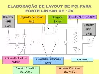
ELABORAÇÃO DE LAYOUT DE PCI PARA FONTE LINEAR DE 12V. Conector KRE 2 vias. Regulador de Tensão 7812. Dissipador SK104. Resistor 1k2 R – 1/3 W. Conector KRE 2 vias. 4 Diodos Retificadores 1N4007. 2 Capacitores Cerâmicos 100 nF. Led Verde. Capacitor Eletrolítico 1000uF/50 V.

E N D
ELABORAÇÃO DE LAYOUT DE PCI PARA FONTE LINEAR DE 12V Conector KRE 2 vias Regulador de Tensão 7812 Dissipador SK104 Resistor 1k2 R – 1/3 W Conector KRE 2 vias 4 Diodos Retificadores 1N4007 2 Capacitores Cerâmicos 100 nF Led Verde Capacitor Eletrolítico 1000uF/50 V Capacitor Eletrolítico 470uF/16 V
COMO IDENTIFICAR UM COMPONENTE NAS BIBLIOTECAS SUGERIDAS C6 600 mils 1/10” = 2,54 mm = 100 mils
IDENTIFICAÇÃO DOS COMPONENTES JUNTO ÀS BIBLIOTECAS Conector KRE 2 vias Regulador de Tensão 7812 Dissipador SK104 Resistor 1k2 R – 1/3 W SK104 Conector KRE 2 vias QM4 R3 D3 D3 C6,5 KRE1 KRE1 C6,5 C4 KRE1 D3 CP2 CP2 D3 D3 LED 4 Diodos Retificadores 1N4007 2 Capacitores Cerâmicos 100 nF Led Verde Capacitor Eletrolítico 1000uF/50 V Capacitor Eletrolítico 470uF/16 V
LIMITAÇÕES DO LAYOUT EM FUNÇÃO DO PROCESSO DE FRESAGEM Espessura das trilhas (lines) R/l = r/A [Ω/m] onde: R é a resistência elétrica; r é a resistividade (ou resistência específica); l é o comprimento; e A é a área da secção transversal reta. Espessura mínima das trilhas: 30 mils Aumento da capacidade de condução em baixas freqüências Dado empírico: 1/40 A/mils
LIMITAÇÕES DO LAYOUT EM FUNÇÃO DO PROCESSO DE FRESAGEM Dimensões mínimas das ilhas (pads) e vias em relação aos eixos coordenados X e Y Dimensões mínimas em relação aos eixos coordenados X e Y: 80 mils
LIMITAÇÕES DO LAYOUT EM FUNÇÃO DO PROCESSO DE FRESAGEM Distância mínima necessário ao isolamento Distância mínima para reconhecimento de isolamento (ilha-ilha, ilha-trilha, trilha-trilha, etc): 10 mils
LIMITAÇÕES DO LAYOUT EM FUNÇÃO DO PROCESSO DE FRESAGEM Espessura mínima das trilhas Dimensões mínimas em relação aos eixos coordenados X e Y Distância mínima para reconhecimento de isolamento (pad-pad, pad-trilha, trilha-trilha, etc)