Chapter 5 Overview
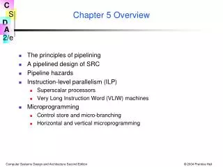
Chapter 5 Overview. The principles of pipelining A pipelined design of SRC Pipeline hazards Instruction-level parallelism (ILP) Superscalar processors Very Long Instruction Word (VLIW) machines Microprogramming Control store and micro-branching Horizontal and vertical microprogramming.

Chapter 5 Overview
E N D
Presentation Transcript
Chapter 5 Overview • The principles of pipelining • A pipelined design of SRC • Pipeline hazards • Instruction-level parallelism (ILP) • Superscalar processors • Very Long Instruction Word (VLIW) machines • Microprogramming • Control store and micro-branching • Horizontal and vertical microprogramming
Bölüm 5 Genel Bakış Pipeline mimarisinin esasları SRC nin pipeline tasarımı Pipeline riskleri Instruction-level parallelism (ILP) Superscalar işlemciler Very Long Instruction Word (VLIW) makineleri Microprogramming Control store ve micro-branching Horizontal(Yatay)ve vertical(Dikey) microprogramming
Fig 5.1 Executing Machine Instructions vs. Manufacturing Small Parts
The Pipeline Stages • 5 pipeline stages are shown • 1. Fetch instruction • 2. Fetch operands • 3. ALU operation • 4. Memory access • 5. Register write • 5 instructions are executing • shr r3, r3, 2 ;storing result in r3 • sub r2, r5, r1 ;idle, no mem. access needed • add r4, r3, r2 ;adding in ALU • st r4, addr1 ;accessing r4 and addr1 • ld r2, addr2 ;instruction being fetched
Pipeline Aşamaları 5 pipeline aşaması 1. Fetch instruction 2. Fetch operands 3. ALU işlemleri 4. Bellek erişimi 5. Register yazma 5 komut işleniyor shr r3, r3, 2 ;sonuç r3 e depolanır sub r2, r5, r1 ;idle, bellek ulaşımına gerek yok add r4, r3, r2 ;ALU da toplama st r4, addr1 ;r4 ve addr1 e ulaşılması ld r2, addr2 ;komutun getirilmesi
Notes on Pipelining Instruction Processing • Pipeline stages are shown top to bottom in order traversed by one instruction • Instructions listed in order they are fetched • Order of insts. in pipeline is reverse of listed • If each stage takes one clock: - every instruction takes 5 clocks to complete - some instruction completes every clock tick • Two performance issues: instruction latency, and instruction bandwidth
Pipeline Komut İşleme Pipeline stages are shown top to bottom in order traversed by one instruction Komutlar fetch edildiği sırada listelenir. Pipeline da komutlarun sırası listenin tersinedir. Eğer her aşama bir clock tutarsa: - her komut 5 clock da tamamlanır - her clock da komut bitimi İki performans konusu: komut gecikme süresi, ve komut bant genşiliği
Dependence Among Instructions • Execution of some instructions can depend on the completion of others in the pipeline • One solution is to “stall” the pipeline • early stages stop while later ones complete processing • Dependences involving registers can be detected and data “forwarded” to instruction needing it, without waiting for register write • Dependence involving memory is harder and is sometimes addressed by restricting the way the instruction set is used • “Branch delay slot” is example of such a restriction • “Load delay” is another example
Komutlar Arasındaki Bağımlılık Pipeline da bazı komutların işlenmesi, diğerlerinin bitimine bağlıdır. Bir çözüm “stall” (bekletme) dir İlk aşamalar, sonrakiler işlemlerini bitirirken, beklerler. Register ları içeren bağlılıklar, register yazması beklenmeden, tespit edilebiilir ve veri kendine ihitiyaç olunan komuta forward edilir. Bellek içeren bağlılıklar daha zordur ve kullanılacak komut kümesi yolunda kıstlamalar oluşturabilir. “Branch delay slot” bu tip bir kıstlamaya örnek olabilie. “Load delay” bir diğer örnektir
Branch and Load Delay Examples Branch Delay • Working of instructions not changed, but way they work together is brz r2, r3 add r6, r7, r8 st r6, addr1 This inst. always executed Only done if r3 0 Load Delay ld r2, addr add r5, r1, r2 shr r1,r1,4 sub r6, r8, r2 This inst. gets “old” value of r2 This inst. gets r2 value loaded from addr
Branch ve Load Gecikme Örnekleri Komutların çalışması değişmez, fakat birlikte çalışma yolu değişebilir. Branch Gecikmesi brz r2, r3 add r6, r7, r8 st r6, addr1 Bu komut herzaman işlenir Sadece r3, 0 olmazsa (r3 0) Load Gecikmesi ld r2, addr add r5, r1, r2 shr r1,r1,4 sub r6, r8, r2 Bu komut r2 nin eski değerini alır Bu komut addr den r2 ye yüklenen değeri alır
Characteristics of Pipelined Processor Design • Main memory must operate in one cycle • This can be accomplished by expensive memory, but • It is usually done with cache, to be discussed in Chap. 7 • Instruction and data memory must appear separate • Harvard architecture has separate instruction & data memories • Again, this is usually done with separate caches • Few buses are used • Most connections are point to point • Some few-way multiplexers are used • Data is latched (stored in temporary registers) at each pipeline stage—called “pipeline registers.” • ALU operations take only 1 clock (esp. shift)
Pipeline İşlemci Tasarımının Özellikleri Ana bellek tek cycle da işlenmeli Pahalı bellek kullanılması gerekir, fakat Bu işlem cache ile genelde yapılır , to be discussed in Chap. 7 Komut ve veri belleği ayrı görülmelidir Harvard mimarisi ayrı komut ve veri belleklerine sahiptir. Bu genelde ayrı cache lerde yapılır. Az miktar da veri yolu kullanılır Pek çok bağlantı point to point dir. Bazı few-way multiplexers(çoklayıcı)kullanılır. Veri, her pipeline aşamasında tutulur (geçici registera depolanır)—called “pipeline registers.” ALU işlemleri sadece 1 clock alır. (esp. shift)
Adapting Instructions to Pipelined Execution • All instructions must fit into a common pipeline stage structure • We use a 5 stage pipeline for the SRC 1) Instruction fetch 2) Decode and operand access 3) ALU operations 4) Data memory access 5) Register write • We must fit load/store, ALU, and branch instructions into this pattern
Komutların Pipeline Olarak İşlenmeye Adapte Edilmesi Bütün komutlar genel bir pipeline aşama yapısına uymak zorundadır. Biz SRC için 5 aşamalı pipeline mimarisi kullancağız 1) Instruction fetch 2) Decode ve operand ulaşımı 3) ALU işlemleri 4) Veri Belleğine Ulaşım 5) Register yazma Biz load/store, ALU ve branch komutlarını bu yapıya uyğun hale getireceğiz.
Fig 5.2 ALU Instructions fit into 5 Stages • Second ALU operand comes either from a register or instruction register c2 field • Op code must be available in stage 3 to tell ALU what to do • Result register, ra, is written in stage 5 • No memory operation
Fig 5.2 ALU Komutu 5 aşamada • İkinci ALU işlemi register dan veya c2 den gelebilir. • Op code 3. aşamada ALU ya ne yapılacağını söylemesi için hazır olmalıdır. • Somuç registeri ra ya 5. aşamada yazılır. • Bellek işlemi yoktur.
Fig 5.4 Load and Store Instructions • ALU computes effective addresses • Stage 4 does read or write • Result reg. written only on load
Fig 5.4 Load ve Store Komutları ALU computes effective addresses Aşama 4 read veya write yapar Sonuç reg. Sadece load da yazılır.
Fig 5.6 SRC Pipeline Registers and RTN Specification • The pipeline registers pass info. from stage to stage • RTN specifies output reg. values in terms of input reg. values for stage • Discuss RTN at each stage on blackboard
Fig 5.6 SRC Pipeline Registers and RTN Specification pipeline registerlar aşamadan aşamaya bilgi geçirirler. RTN aşamlar için output reg. değerlerini, input reg değerleri açısından belirtir. Discuss RTN at each stage on blackboard
Global State of the Pipelined SRC • PC, the general registers, instruction memory, and data memory is the global machine state • PC is accessed in stage 1 (& stage 2 on branch) • Instruction memory is accessed in stage 1 • General registers are read in stage 2 and written in stage 5 • Data memory is only accessed in stage 4
Pipeline SRC de Global State PC, the general registers, komut belleği, and veri belleği global makine durumudur. PC ye aşama 1 de ulaşılır. (& aşama 2 on branch) Komutbelleğine ye aşama 1 de ulaşılır. Genel registers aşama 2 de okunur ve aşama 5 de yazılır. Veri belleğine sadece aşama 4 de ulaşılır.
Restrictions on Access to Global State by Pipeline • We see why separate instruction and data memories (or caches) are needed • When a load or store accesses data memory in stage 4, stage 1 is accessing an instruction • Thus two memory accesses occur simultaneously • Two operands may be needed from registers in stage 2 while another instruction is writing a result register in stage 5 • Thus as far as the registers are concerned, 2 reads and a write happen simultaneously • Increment of PC in stage 1 must be overridden by a successful branch in stage 2
Pipeline: Global State e ulaşımda ki Kısıtlamalar Neden ayrı komut ve veri bellekleri kullandığımızı gördük Bir load veya store komutu stage 4 de veri belleğine ulaşırken, aşama 1 de bir komut a ulaşılır. Böylece iki bellek ulaşımı eş zamanlı meydana gelir. Aşama 2 de register ların 2 tane operand ihtiyacı varken, bir diğer komut aşama 5 de sonuç register ına veri yazar. Böylece 2 read ve 1 write işlemi eş zaamnlı olarak gerçekleşir. Aşama 2 deki başarılı bir branch işlemi, aşama 1 de PC nin artırılmasını zorunlu kılar.
Fig 5.7 Pipeline Data Path & Control Signals Most control signals shown and given values Multiplexer control is stressed in this figure
Fig 5.7 Pipeline Data Path & Control Signals • Pek çok kontrol sinyali ve değerleri • Çoklayıcı kontrolü bu figürde ön plana çıkartılmıştır.
Example of Propagation of Instructions Through Pipe 100: add r4, r6, r8; R[4] R[6] + R[8]; 104: ld r7, 128(r5); R[7] M[R[5]+128]; 108: brl r9, r11, 001; PC R[11]: R[9] PC; 112: str r12, 32; M[PC+32] R[12]; . . . . . . 512: sub ... next instruction • It is assumed that R[11] contains 512 when the brl instruction is executed • R[6] = 4 and R[8] = 5 are the add operands • R[5] =16 for the ld and R[12] = 23 for the str
Pipe İşleminde komutların yayılmasına örnekler brl komutu işlendiği zaman, R[11] in 512 içermesi beklenir R[6] = 4 ve R[8] = 5 add operandlarıdır. R[5] =16 ld içinve R[12] = 23 str için 100: add r4, r6, r8; R[4] R[6] + R[8]; 104: ld r7, 128(r5); R[7] M[R[5]+128]; 108: brl r9, r11, 001; PC R[11]: R[9] PC; 112: str r12, 32; M[PC+32] R[12]; . . . . . . 512: sub ... Sonraki komut
Fig 5.8 Cycle 1 add Enters Pipe • Program counter is incremented to 104 512: sub ... . . . . . . 112: str r12, #32 108: brl r9, r11, 001 104: ld r7, r5, #128 100: add r4, r6, r8
Fig 5.8 Cycle 1 add Enters Pipe PC 104 e artıtılır. 512: sub ... . . . . . . 112: str r12, #32 108: brl r9, r11, 001 104: ld r7, r5, #128 100: add r4, r6, r8
Fig 5.9 Cycle 2ld Enters Pipe • add operands are fetched in stage 2 512: sub ... . . . . . . 112: str r12, #32 108: brl r9, r11, 001 104: ld r7, r5, #128 100: add r4, r6, r8
Fig 5.9 Cycle 2ld Enters Pipe Aşama 2 de add operandları getirildi. 512: sub ... . . . . . . 112: str r12, #32 108: brl r9, r11, 001 104: ld r7, r5, #128 100: add r4, r6, r8
Fig 5.10 Cycle 3 brl Enters Pipe • add performs its arithmetic in stage 3 512: sub ... . . . . . . 112: str r12, #32 108: brl r9, r11, 001 104: ld r7, r5, #128 100: add r4, r6, r8
Fig 5.10 Cycle 3 brl Enters Pipe Aşama 3 de add aritmetik işlemini yerine getirir 512: sub ... . . . . . . 112: str r12, #32 108: brl r9, r11, 001 104: ld r7, r5, #128 100: add r4, r6, r8
Fig 5.11 Cycle 4str enters pipe • add is idle in stage 4 • Success of brl changes program counter to 512 512: sub ... . . . . . . 112: str r12, #32 108: brl r9, r11, 001 104: ld r7, r5, #128 100: add r4, r6, r8
Fig 5.11 Cycle 4str enters pipe add aşama 4 deki gibi aynıdır Brl PC yi 512 ye değiştirir. 512: sub ... . . . . . . 112: str r12, #32 108: brl r9, r11, 001 104: ld r7, r5, #128 100: add r4, r6, r8
Fig 5.12 Cycle 5 sub Enters Pipe • add completes in stage 5 • sub is fetched from loc. 512 after successful brl 512: sub ... . . . . . . 112: str r12, #32 108: brl r9, r11, 001 104: ld r7, r5, #128 100: add r4, r6, r8
add aşama 5 de tamamlanır Brl den sonra, sub 512 location ından alıp getirilir. Fig 5.12 Cycle 5 sub Enters Pipe 512: sub ... . . . . . . 112: str r12, #32 108: brl r9, r11, 001 104: ld r7, r5, #128 100: add r4, r6, r8
Functions of the SRC Pipeline Stages • Stage 1: fetches instruction • PC incremented or replaced by successful branch in stage 2 • Stage 2: decodes inst. and gets operands • Load or store gets operands for address computation • Store gets register value to be stored as 3rd operand • ALU operation gets 2 registers or register and constant • Stage 3: performs ALU operation • Calculates effective address or does arithmetic/logic • May pass through link PC or value to be stored in mem.
SRC Pipeline Aşamalrının Fonksiyonları Aşama 1: komutun alıp getirilmesi (fetch) PC arttırılır veya aşama 2 de başarılı bir branch (dallanma) ile yenilenir. Aşama 2: komutun decode edilmesi ve operandların alınması Load veya store, adres hesaplaması için operandalrı alır Store 3. operand olarak depolancak register değerini alır ALU işlemi 2 register veya 1 register ve 1 sabit alır. Aşama 3: ALU işleminin gerçekleştirilmesi Effective adres hesaplanır veya arithmetic/logic işlemler yapılır PC veya bellekde depolanmış degere geçiş olabilir.
Functions of the SRC Pipeline Stages (continued) • Stage 4: accesses data memory • Passes Z4 to Z5 unchanged for non-memory instructions • Load fills Z5 from memory • Store uses address from Z4 and data from MD4(no longer needed) • Stage 5: writes result register • Z5 contains value to be written, which can be ALU result, effective address, PC link value, or fetched data • ra field always specifies result register in SRC
SRC Pipeline Aşamalrının Fonksiyonları Aşama 4: veri belleğine ulaşılması Bellek kullanılmayan komutlarda Z4 ve Z5 değişmeden geçilir. Store,Z4 den adres ve MD4 den veriyi kullanır Aşama 5: sonuç registerin yazılması Z5 yazılacak değeri tutar, bu değer ALU result, effective address, PC link value, veya fetched data olabilir. SRC de ra alanı genelde sonuç register olarak belirtilir.
Dependence Between Instructions in Pipe: Hazards • Instructions that occupy the pipeline together are being executed in parallel • This leads to the problem of instruction dependence, well known in parallel processing • The basic problem is that an instruction depends on the result of a previously issued instruction that is not yet complete • Two categories of hazards Data hazards: incorrect use of old and new data Branch hazards: fetch of wrong instruction on a change in PC
Komutlar Arasındaki Bağlılıklar in Pipe: Hazards Pipeline da komutlar paralel olarak işletilir. Paralel işlemede, bu durum komutların birbirine bağlılık problemine sebep olur. Temel problem, bir komutun çalışmasının, çalışmasını bitirmemiş başka bir komutun işlenmesi sonucu ortaya çıkacak olan sonuca bağlı olmasından ileri gelir. Hataları iki kategoride inceleriz Veri hazards: eski ve yeni verinin yanlış kullanımı Dallanma (Branch) hazards: PC de ki değişim sonucunda yanlış komutun fetch edilmesi
General Classification of Data Hazards(Not Specific to SRC) • A read after write hazard (RAW) arises from a flow dependence, where an instruction uses data produced by a previous one • A write after read hazard (WAR) comes from an anti-dependence, where an instruction writes a new value over one that is still needed by a previous instruction • A write after write hazard (WAW) comes from an output dependence, where two parallel instructions write the same register and must do it in the order in which they were issued
Veri Hazard larının Genel Sınıflandırılması A read after write hazard (RAW) arises from a flow dependence, bir komutun bir önceki komut tarafından oluşturulan veriyi kullanması gereken durumda oluşur. A write after read hazard (WAR) comes from an anti-dependence, bir komutun yeni bir değeri bir yere yazarken, oradan hala bir önceki komutun değer alması gerekiyorsa oluşur. A write after write hazard (WAW) comes from an output dependence, iki paralel komutun aynı registera yazma durumları varsa, bu işlemleri işleme sırasına göre yapmalrı gerekir.
Detecting Hazards and Dependence Distance • To detect hazards, pairs of instructions must be considered • Data is normally available after being written to reg. • Can be made available for forwarding as early as the stage where it is produced • Stage 3 output for ALU results, stage 4 for mem. fetch • Operands normally needed in stage 2 • Can be received from forwarding as late as the stage in which they are used • Stage 3 for ALU operands and address modifiers, stage 4 for stored register, stage 2 for branch target
Hataların Tespit Edilmesi ve Bağımlılık Mesafesi Hataların ayıklanması için komut çifti bilinmelidir Veri normalde reg. e yazıldıktan sonra uygun olur. “Forwarding” işlemi aşamalarda gerektiği anda en erken biçimde yapılmalıdır aşama 3 ALU sonucu için output, aşama 4 bellek fetch için Operandlar normalde aşama 2 için ihtiyaç olurlar Can be received from forwarding as late as the stage in which they are used Aşama 3 ALU operandları ve adres modifierları için, aşama 4 depolama register için, aşama 2 branch target için
Data Hazards in SRC • Since all data memory access occurs in stage 4, memory writes and reads are sequential and give rise to no hazards • Since all registers are written in the last stage, WAW and WAR hazards do not occur • Two writes always occur in the order issued, and a write always follows a previously issued read • SRC hazards on register data are limited to RAW hazards coming from flow dependence • Values are written into registers at the end of stage 5 but may be needed by a following instruction at the beginning of stage 2