Download
1 / 43
630 likes | 1.43k Vues
Development of 1200kV Transmission System in India. V Ramakrishna, Central Electricity Authority Subir Sen, Power Grid Corpn. of India Ltd. Presentation Flow. Overview of Indian Power System Future demand-supply scenario

E N D
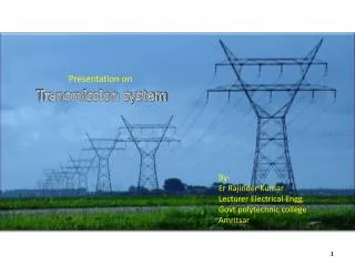
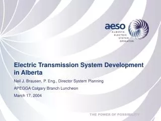
Development of 1200kV Transmission System in India V Ramakrishna, Central Electricity Authority Subir Sen, Power Grid Corpn. of India Ltd.
Presentation Flow • Overview of Indian Power System • Future demand-supply scenario • Consideration for high capacity 1200kV transmission corridor development • Broad 1200kV AC technical parameters • 1200kV UHVAC Test Station • Summary
Indian Power System - Present • Installed Capacity: 147GW • Peak Demand : 109 GW • Transmission Grid Comprises: • 765kV Lines - 1600 ckt. km • 400kV Lines - 76,000 ckt. km • 220/132kV Lines - 115,000 ckt. km • HVDC bipoles - 3 nos. • HVDC back-to-back - 7 nos. • FSC – 18 nos. • TCSC – 6 nos. • NER, ER, NR & WR operating as single grid of 100 GW • SR Grid – 40 GW • Inter-regional capacity : 18,700 MW
National Grid - At Present North-eastern Region Eastern Region Northern Region 1260 MW 6330 MW 2120 MW Western Region 2990MW 1720 MW 3630 MW Southern Region Inter-regional Capacity - 18,700MW (incl. 132kV links)
Inter-regional capacity : 18,700MW National Grid - Present
National Grid by 2012 6000 MW Northern Region Eastern Region North-eastern Region 2860 MW 12130 MW 4220 MW Western Region 6490 MW 2720 MW 3630 MW Southern Region Inter-regional Capacity - 38,700MW (incl. 132kV links)
National Grid by 2012 Inter-regional capacity : 38,700 MW National Grid – A Continuing Process
Energy Resource Map • Hydro potential in NER and upper part of NR • Coal reserves mainly in ER • Ensure optimal utilisation of resources – strong National Grid is in place and capacity is being enhanced continuously
Likely Capacity addition in next 15 years • Peak Demand : 450GW • Inst. Capacity : 600GW • Additional capacity addition of about 390GW would be required Load centre based, 90
Future Demand-Supply Scenario Region Installed Capacity (GW) Availability (GW) Peak Demand (GW) Surplus(+) /Deficit (-) GW Northern 145 110 140 (-) 30 Western 135 100 130 (- ) 30 Southern 135 100 130 (- ) 30 Eastern 105 80 40 (+) 40 North-eastern 80 60 10 (+) 50 Total 600 450 450
Likely power transfer requirement between various regions in next 15 years 18 GW North-eastern Region IC = 80 GW Despatch = 60 GW Demand = 10 GW Surplus = 50 GW Northern Region 27 GW IC = 145 GW Despatch = 110 GW Demand = 140 GW Deficit = 30 GW 20 GW 12 GW Eastern Region 10,000MW IC = 106 GW Despatch = 80 GW Demand = 40 GW Surplus = 40 GW Western Region 23 GW ALL INDIA IC = 600 GW Demand = 450 GW IC = 135 GW Despatch = 100 GW Demand = 130 GW Deficit = 30 GW 15 GW 15 GW IC = 135 GW Despatch = 100 GW Demand = 130 GW Deficit = 30,GW Southern Region
Power Transfer Requirement by 2014-15 Jharkhand-8000MW 3,000MW 12,500MW NER NR ER IC = 74,000MW Demand = 56,500MW Deficit = -19,000MW 4,000MW IC = 6,300MW Demand = 3,000MW Surplus = 2,500MW 3,000MW IC = 63,000MW Demand = 23,000MW Surplus = 18,000MW 6,000MW 1,000MW 7,500MW 5,000MW 1,000MW Sterlite:2400MW 17,000MW Monet:900MW Jindal:1320MW Malaxmi:956MW Visa:500 MW KVK:560MW Lanco:693MW WR IC = 85,000MW Demand = 55,000MW Deficit = -6,000MW 4,000MW Orissa-7330MW 10,000MW 2,500MW 1,000MW 4,000MW 1,000MW 1,000MW Chattishgarh:8000MW Existing/Planned Being Planned IC = 68,000MW Demand = 49,000MW Surplus = 6,000MW SR A.P. : 12000MW Tamil Nadu : 7000MW
Consideration for Future Transmission Development 1.Requirement of Bulk power transfer over Long Distances from resources rich area/region to load centers 2. ROW constraints, limited Transmission corridors available 3. High Short Circuit Levels 4. Variation and regulation in Power Flow
Power Flow Pattern • Variation in generation • High hydro in monsoon and summer • In winter only during peak hours • Power flow variations due to commercial/operational reasons • Variation in load demand • Daily basis (peak and off-peak) • Seasonal variations Due to above, each transmission corridor has varied power flow pattern ranging from high to low loading, results into wide variation in voltages
Present Technologies & its Limitations • 400 kV Twin Moose - upto 600-700MW • 400 kV Quad Moose - Upto 1200-1500MW • 765 kV Line - upto 2000/3000 MW • Sipat – Seoni first 765 kV line operated at rated voltage • HVDC bipole - + 500 kV upto 2000-2500MW
Need 1.Development of hybrid transmission system for maintaining critical parameters as well as regulations of power flow 2. Increase in MW flow per metre of ROW 3. Controlling high Short Circuit Levels
Transmission System through Narrow Area • Requirement of Power Flow between NER & ER/WR/NR: 50 GW • Required Transmission Capacity : 57.5 GW (15% redundancy) • Existing & planned Capacity : 9.5 GW • Additional Trans. Capacity to be planned : 48 GW Options : 1. +800kV HVDC : 8nos. 2. +800kV HVDC : 5nos.; 765kV EHVAC : 6nos. 3. +800kV HVDC : 4nos.; 1200kV UHVAC : 2nos. • Selection of Next Level Transmission Voltage i.e. 1200kV UHVAC in view of : • Loading lines upto Thermal Capacity(10000 MW) compared to SIL(6000 MW) • Saving Right of Way Eastern Region/ Western Region/ Southern Region North-eastern Region 50 GW
1200kV AC Transmission System – Considerations • In Chhattisgarh State, projects with total capacity of about 35,000 MW have been planned to be commissioned progressively in the next 4-5 years. • Power from these projects is to be transferred to bulk load centres in the Western and Northern Regions. • To facilitate exchange of such quantum of power, strengthening of East-West and East-North transmission corridors in WR is required. • Further, it has been observed that growth of interconnection at 400kV/765kV level would result into increase in short circuit level at various EHV substations beyond the limit (40kA)
1200kV AC Transmission System – A Case Study • Considering quantum of power transfer on long-term as well as to address high short circuit level, a high capacity 1200kV transmission corridor i.e, Raipur-Wardha and Wardha- Aurangabad is proposed • Projects are being developed in a phased manner with less power transfer requirement initially, it is proposed that this high capacity East-West transmission corridor shall be operated initially at 400kV level. Accordingly, with suitable design 1200kV S/c line is initially proposed to be operated as a 400kV (quad) D/c line so that system redundancy can be maintained. Subsequently, with the increase in power transfer requirement through this corridor, line shall be operated at 1200kV level
Line Parameters • Line parameters of 1200kV/765kV/400kV Transmission System Base kV :1200kV/765kV/400kV; Base MVA :100 MVA
Large Variation of Reactive MVAR • Reactance of 1200kV AC line is 1/3rd of 765kV system • Susceptance (charging capacitance) is 2½ times more of 765kV line • Wide difference in the electrical parameters shall lead to the problems of reactive power (VAR) balance • Huge Reactive Power Generation by 1200kV line about 6 MVAR/km • These uncompensated lines shall generate huge capacitive charging reactive power for which static reactive compensation devices like shunt reactor, bus reactor of adequate size is to be provided
1200kV Wardha – Aurangabad line reactive power characteristic
Reactive Power Management of 1200kV Lines Reactive Power Management of 1200kV Lines • Maintaining constant/optimum level of power flow on the 1200kV AC system under different operating conditions • To control power through 1200kV AC system a layered system of 1200kV AC transmission corridor along with 800kV, 6000MW HVDC system shall be developed • Control and regulation mechanisms • Exchange of power between 1200kV AC system and lower level network (765kV/400kV) through HVDC back-to back links at strategic locations • Control of power flow on the 800kV HVDC bipole lines • Dynamic Reactive Power Management through Series and Shunt Compensation
Maintaining Uniform power flow through 1200kV System ~ 800kV HVDC 800kV HVDC 765kV EHVAC System 500kV HVDC 500kV HVDC ~ 400kV EHVAC System 220kV/132kV SYSTEM Layered high capacity transmission network with control & regulation features 1200kV UHVAC System
Increase in Short Circuit Level • Indian system is designed for max. short circuit level – 40kA • After 30 years of operation, it is expected that fault level at various S/s shall increase beyond its limit in next 4-5 years • Most of these s/s are either major pooling stations or high capacity trans. Interconnections with major generation complex/substations • Development of 1200kV transmission corridors shall facilitate in controlling high short circuit level, although other mitigating measures are also being taken
Other 1200kV Parameters Based on the preliminary studies, broad parameters determined as under :
Field Studies on 1200kV AC System • POWERGRID has undertaken various studies and tests to determine the configuration of its 1200kV transmission lines, like • corona cage studies • air gap insulation studies • tests for voltage distribution on the insulator string • long term studies on test line for measurement of AN, RIV & voltage gradient measurement at ground level
Establishment of 1200 kV AC Test Station • To develop 1200kV technology indigenously, POWERGRID in collaboration with manufacturers establishing a 1200kV AC Test Station at Bina • This endeavour shall benefit the Indian Power sector and manufacturers for • Optimisation of transmission cost • Ease in O&M
1200KV UHVAC Test Station • A 3 phase 1200kV Test Lines (S/C & D/C) of about 1 km length are being constructed. Salient features: • Variable Phase to Phase Spacings • Variable Ground Clearance • Upto 12 sub-conductor bundle • Variable Bundle diameter • A 1200kV 3-phase test bay is being constructed to charge these Test Lines
1200KV UHVAC Test Station • Test station shall be fully equipped with testing instrument for field testing • Extensive developmental tests shall be conducted on the test line as well as on s/s equipments installed in the Test Bay jointly by Utilities, Manufacturer & Research Institute
Summary • To meet growing power transfer requirement and environmental friendly development, 1200kV AC system along with 800kV, 6000MW HVDC system has been planned in the Indian Power System • Reactive power management for 1200kV AC system is an important aspect which require detail analysis for suitable static and dynamic reactive compensation • Results of some of preliminary studies discussed • More studies and field tests are under process to finalise all the critical electrical parameters • Establishment of a 1200kV AC Test Station at Bina is under progress
Thank You Thank You