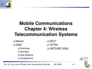
Chapter 4: Telecommunication Systems
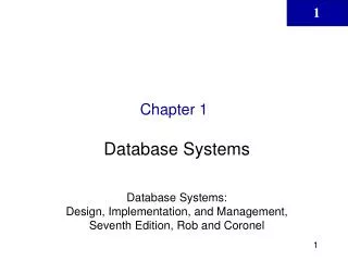
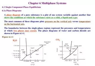
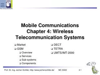
Chapter 4: Telecommunication Systems. Mobile phone subscribers worldwide. approx. 1.7 bn. 1600. 2009: >4 bn!. 1400. 1200. GSM total. 1000. TDMA total. CDMA total. Subscribers [million]. PDC total. 800. Analogue total. W-CDMA. 600. Total wireless. Prediction (1998). 400. 200.

Chapter 4: Telecommunication Systems
E N D
Presentation Transcript
Mobile phone subscribers worldwide approx. 1.7 bn 1600 2009: >4 bn! 1400 1200 GSM total 1000 TDMA total CDMA total Subscribers [million] PDC total 800 Analogue total W-CDMA 600 Total wireless Prediction (1998) 400 200 0 1996 1997 1998 1999 2000 2001 2002 2003 2004 year
Development of mobile telecommunication systems CT0/1 FDMA AMPS CT2 NMT IMT-FT DECT IS-136 TDMA D-AMPS EDGE IMT-SC IS-136HS UWC-136 TDMA GSM GPRS PDC IMT-DS UTRA FDD / W-CDMA HSPA IMT-TC UTRA TDD / TD-CDMA IMT-TC TD-SCDMA CDMA IS-95 cdmaOne IMT-MC cdma2000 1X EV-DO cdma2000 1X 1X EV-DV (3X) 2G 3G 1G 2.5G
What is GSM? • The Global System for Mobile Communications is a digital cellular communications system. • It was developed in order to create a common European mobile telephone standard but it has been rapidly accepted worldwide. • GSM was designed to compatible with ISDN (integrated services digital network) services. • It signifies an extremely successful technology and bearer for mobile communication system. • GSM today Covers 71% of all the digital wireless market.
What is GSM? People use it not only in business but also in everyday personal life. Its principle use it is for wireless telephony and messaging through SMS. It also supports facsimile and data communication. Due to its innovative technologies and strengths GSM rapidly became truly global. Many of the new standardization initiative came from outside Europe.
What is GSM? Depending on locally available frequency bands, different air interfaces were defined. These are 900MHz, 1800MHz, and 1900MHz. However, architecture, protocols, signaling and roaming are identical in all networks independent of the operating frequency bands. GSM uses a combination of FDMA (frequency division multiple access) and TDMA ( Time division multiple access).
Why GSM? GSM uses radio frequencies more effectively than the older system. The data transmission services and the quality of the speech are better than in analog system. There are two kinds of advanced security services available on the radio path : user identity and data confidentiality. New services and ISDN compatibility are offered. It makes international roaming possible. The big uniform market hardens the competitions and lowers the prices. Later on it also leads to lower system costs.
History of GSM GSM is based on a set of standards, formulated in the early 1980s. In 1982 the conference of European posts and Telegraphs formed a study group called the Groupe Special Mobile (GSM) to study and develop a pan-European mobile system, which was later introduce as Global System for Mobile Communication.
GSM Services GSM offers several types of connections voice connections, data connections, short message service multi-service options (combination of basic services) Three service domains Bearer Services Tele Services Supplementary Services
GSM Services (cont…) TE=Terminal MT=Mobile Termination PLMIN=public land mobile network PSTN=public switched telephone network ISDN=integrated services digital network bearer services MS GSM-PLMN transit network (PSTN, ISDN) source/ destination network TE MT TE R, S Um (U, S, R) tele services Fig: Bearer and Tele services referene model
GSM Services: Tele Services Telecommunication services that enable voice communication via mobile phones. All these basic services have to obey cellular functions, security measurements etc. Telephony Facsimile group 3 Emergency call Teletex Short message Services (SMS) Fax mail Voice mail Electronic mail
GSM Services: Bearer Services A bearer service is used for transporting user data. Some of the bearer services are listed below: Asynchronous and Synchronous data, 300-9600 bps. Alternate speech and data, 300-9600 bps. Asynchronous PAD (packet-switched access, 300-9600 bps. Synchronous dedicated packet data access, 2400-9600 bps.
GSM Services:Supplementary Services Call Forwarding- the subscriber can forward incoming calls to another number if the called mobile is busy, unreachable or if there is no reply. Call Barring-There are different types of call barring services: Barring of all outgoing calls Barring of outgoing international calls Barring of all incoming calls Barring of incoming calls when roaming. Call hold-puts an active call on hold.
GSM Services:Supplementary Services Call Waiting Closed user group, CUG-it corresponds to a group of users with limited possibilities of calling, locking of the mobile terminal (Incoming and outgoing calls)
GSM Architecture The coverage area of a cellular system is partitioned into a number of smaller area or cells with each cell served by a Base Station (BS) for radio coverage. The base station are connected through fixed links to a mobile switching center (MSC), which is a local switching exchange with additional features to handle mobility management requirements of a cellular system.
GSM Architecture MSCs also interconnect with the public switched telephone network (PSTN) because the majority of calls in a cellular mobile system either originate form or terminate at fixed network terminals. In the next slide figure a typical cellular system architecture/ GSM network architecture.
GSM: elements and interfaces radio cell BSS MS MS Um radio cell MS RSS BTS BTS Abis BSC BSC A MSC MSC NSS VLR VLR signaling HLR ISDN, PSTN GMSC PDN IWF O OSS EIR AUC OMC
GSM Architecture GSM system consist of three subsystems: Radio Subsystem (RSS) Network and Switching Subsystem (NSS) Operation Subsystem (OSS)
GSM Architecture:Radio Subsystem (RSS) Mobile Station: Mobile station consist of two units: Mobile hand set is one of the most complicated GSM device. It provides user the access to the network. Subscribe identity module (SIM) is a removable module goes into the mobile handset. Each SIM has unique number called international mobile subscriber identity (IMSI). It has built in micro-computer & memory into it.
GSM Architecture:Radio Subsystem (RSS) Base station subsystem (BSS): A GSM network comprises many BSS, each controlled by a base station controller (BSC). The BSS performs all function necessary to maintain radio connections to an MS, coding/decoding of voice, and rate adaptation to/from the wireless network part. Besides a BSC, the BSS contains several BTS.
GSM Architecture:Radio Subsystem (RSS) Base transceiver station (BTS): BTS has set of transceiver to talk to MS. One BTS covers one or more than one cell. Capacity of BTS depends on no of transceivers. BTS is connected to BSC via A’bis interface. Transmission rate on A’bis is 2 Mbps. Interface between MS and BTS is called Um. Transmission rate on Um interface is 13 Kbps. Each transmission has 8 TDMA channels to carry voice & signaling.
GSM Architecture:Radio Subsystem (RSS) Base station controller (BSC): BSC controls several BTSs. BSC manages channel allocation & handover of called from one BTS to another BTS. BSC is connected to MSC via A’ interface. Transmission rate on A I/F is 2 Mbps. Interface between BSC & BTS is called A’bis I/F. BSC has database for all of its BTS’s parameters. BSC provides path from MS to MSC.
GSM Architecture:Network and Switching Subsystem (NSS) Mobile services switching center (MSC): MSC is hear of the entire network connecting fixed line network to mobile network. MSC manages all call related functions and billing information. MSC is connected to HLR & VLR for subscriber identification & routing incoming calls. MSC capacity is in terms of no of subscribers. MSC is connected to BSC at one end and fixed line network on other end. Call Detail Record (CDR) is generated for each & every call in the MSC.
GSM Architecture:Network and Switching Subsystem (NSS) Home location register (HLR): All subscribers data is stored in HLR. It has permanent data base of all the registered subscribers.
GSM Architecture:Network and Switching Subsystem (NSS) Visitor location register (VLR): Active subscriber is registered in VLR. It is a temporary data base of all the active subscribers. HLR validates subscriber before registration. MSC ask VLR before routing incoming call.
GSM Architecture:Operation Subsystem (OSS) Operation and maintenance center (OMC): All the network elements are connected to OMC. OMC monitors health of all network elements & carries out maintenance operation, if required. OMC is linked to BTSs via parent BSC. OMC keeps records of all the faults occurred. OMC can also generate Traffic analysis reports.
GSM Architecture:Operation Subsystem (OSS) Authentication center (AuC): Authentication is a process to verify the subscriber SIM. Secret data & verification algorithm are stored in to the AUC. AUC & HLR combined to authenticate the subscribers. Subscriber authentication can be done on every call if required.
GSM Architecture:Operation Subsystem (OSS) Equipment identity register (EIR): The equipment identity register stores the international mobile equipment identity (IMEI) numbers for the entire network. IMEI enables the MSC in denitrifying the type of terminal, mobile equipment manufacturer, and model and helps the network in locating the device in case it is stolen or misplaced. The EIR contains three different types of lists: A Black list: includes mobile stations which have been reported stolen or are currently locked due to some reason.
GSM Architecture:Operation Subsystem (OSS) Equipment identity register (EIR): A White list: which records all MSs that are valid and operating. A Grey list: including all those MSs that may not be functioning properly. According to category the MS can make calls or can be stopped from making calls.
Radio Interface The radio interface is the interface between the mobile stations and the fixed infrastructure. It is one of the most important interfaces of the GSM system. One of the main objectives of GSM is roaming. Therefore, in order to obtain a complete compatibility between mobile stations and networks of different manufactures and operators, the radio interface must be completely defined.
Radio Interface The spectrum efficiency depends on the radio interface and the transmission, more particularly in aspects as the capacity of the system and the techniques used in order to decrease the interface and to improve the frequency reuse scheme. The specification of the radio interface has then an important influence on the spectrum efficiency.
Radio Interface Frequency allocation: Two frequency band of 25 MHz each one, have been allocated for the GSM system: The band 890-915 MHz has been allocated for the uplink direction (transmitting from the mobile station to the base station) The band 935-960 MHz has been allocated for the down link direction (transmitting from the base station to the mobile station) But not all the countries can use the whole GSM frequency band.
Radio Interface Multiple Access Scheme: The multiple access scheme defines how different simultaneous communications, between different mobile stations situated in different cells, share the GSM radio spectrum. A mix of Frequency Division Multiple Access (FDMA) and Time Division Multiple Access (TDMA) combined with frequency hopping, has been adopted as the multiple access scheme for GSM.
Radio Interface FDMA: Using FDMA, a frequency is assigned to a user. So the larger the number of users in a FDMA system the larger the number of available frequencies must be. The limited available radio spectrum and the fact that a user will not free its assigned frequency until he does not need it anymore, explain why the number of users in a FDMA system can be ‘quickly” limited.
Radio Interface TDMA: On the other hand, TDMA allows several users to share the same channel. Each of the users, sharing the common channel, is assigned their own burst within a group of bursts called a frame. Usually TDMA is used with a FDMA structure.
GSM - TDMA/FDMA higher GSM frame structures 4.615 ms 546.5 µs 577 µs 935-960 MHz 124 channels (200 kHz) downlink frequency 890-915 MHz 124 channels (200 kHz) uplink time GSM TDMA frame 5 7 8 1 2 4 6 3 GSM time-slot (normal burst) guard space guard space S user data tail tail user data S Training 1 3 1 57 bits 3 bits 57 bits 26 bits
Radio Interface Data is transmitted in small portion is called bursts. Each carrier frequency is then divided in time using a TDMA scheme. This scheme splits the radio channel, with a width of 200KHz, into 8 burst. A burst is the unit of time in TDMA system, and its lasts approximately 0.577 ms. A TDMA frame is form with 8 bursts and lasts consequently, 4.615 ms. Each of the eight burst, that form a TDMA frame, are then assigned to a single user.
Radio Interface:Channel Structure A channel corresponds to the recurrence of one burst every frame. It is defined by its frequency and the position of its corresponding burst within a TDMA frame. GSM in TDMA: Each carrier consists of eight time slots. In GSM there are Two types of Channels: Physical Channel: Logical Channel:
Radio Interface:Channel Structure Physical Channel: A physical channel is a single slot on a single frequency. Thus there are eight physical channels per frequency pair of TDMA frame. The information within the physical channel is termed a burst.
Radio Interface:Channel Structure Logical Channel: A logical channel is the content within a burst, e.g. Speech. Signalling or measurement, the way in which we organize these channels is partly dependent upon the application. But is dependent on whether the information is sent uplink or downlink or bi-direction.
Radio Interface:Channel Structure Logical Channel: There are two type of logical channel: The Traffic Channels used to transport speech and data information. The Control Channels used for network management message and some channel maintenance tasks.
Radio Interface:Channel Structure Traffic Channels (TCH): Full-rate traffic channels (TCH/F) are defined using a group of 26 TDMA frame called a 26-multiframe. The 26-multiframe lasts consequently 120 ms. In this 26-multiframe structure the traffic channels for the downlink and uplink are separated by 2 bursts. As a consequence, the mobiles will not need to transmit and receive at the same time which simplifies considerably the electronics of the system.
Radio Interface:Channel Structure Traffic Channels (TCH): The frame that form the 26-multiframe structure have different functions: 24 frames are reserved to traffic. 1 frame is used for the slow associated control channel (SACCH). The last frame is unused. This idle frame allows the mobile station to perform other functions, such as measuring the signal strength of neighboring cells.
Radio Interface:Channel Structure Traffic Channels (TCH): Half-rate traffic channels (TCH/H) which double the capacity of the system, are also grouped in a 26-multifram but the internal structure is different.
Radio Interface:Channel Structure Control Channels: according to their functions, four different classes of control channels are defined: 2.1 Broadcast channels (BCH). 2.2 Common control channels (CCCH). 2.3 Dedicated control channels (DCCH). 2.4 Associated control channels (ACCH).
Radio Interface:Channel Structure 2.1 Broadcast channels (BCH): the broadcast channels are used, by the base station to provide the mobile station with the sufficient information. It needs to synchronize with the network. There are different types of BCH can be distinguished: FCCH (Frequency Correction Channel): it carries no real information. All bits are set to zero, which generates a pure sine wave in the modulator.
Radio Interface:Channel Structure 2.1 Broadcast channels (BCH): FCCH (Frequency Correction Channel): It allows the mobile to tune its synthesizer roughly and indicates that on this frequency broadcast information is transmitted. SCH (Synchronization Channel): The SCH transmits the used for handover and the TDMA frame number which is used for ciphering. BCCH (Broadcast Control Channel): The BCCH contains cell specific information like cell ID, used frequency hopping sequences, adjacent cells etc.
Radio Interface:Channel Structure 2.2 Common control channels (CCCH): The CCCH channels help to establish the calls from the mobile station or the network. There different types of CCCH can be defined: PCH (Paging Channel (Downlink)): This channel transmits the paging request for a mobile in case of an incoming call.
Radio Interface:Channel Structure 2.2 Common control channels (CCCH): AGCH (Access Grant Channel (Downlink)): On this channel the mobile gets initial time advance and the information which signaling channel should be used. RACH (Random Access Channel (Uplink)): Only on this the mobile can access a cell. It contains an identifier of the mobile.
Radio Interface:Channel Structure 2.3 Dedicated control channels (DCCH): The DCCH channels are used for message exchange between several mobiles or a mobile and the network. Two different types of DCCH can be defined: SDCCH (Stand alone dedicated control channel): This channel is bi-directional and is used for cell set up procedures such as authentication and it assigns a particular traffic channel to the mobile.