VOICE CONTROLLED WHEELCHAIR
VOICE CONTROLLED WHEELCHAIR. PROJECT GUIDE: Mr. RAJESH M.V Sr. LECTURER IN ELECTRONICS & COMM PROJECT CO-ORDINATOR: Mrs. JIBI JOHN Sr. LECTURER IN ELECTRONICS & COMM Website: www.techtriks.wordpress.com. Team Members NISHA M.S. ECU032/48

VOICE CONTROLLED WHEELCHAIR
E N D
Presentation Transcript
VOICE CONTROLLED WHEELCHAIR PROJECT GUIDE: Mr. RAJESH M.V Sr. LECTURER IN ELECTRONICS & COMM PROJECT CO-ORDINATOR: Mrs. JIBI JOHN Sr. LECTURER IN ELECTRONICS & COMM Website: www.techtriks.wordpress.com Team Members NISHA M.S. ECU032/48 SAPNA VASUDEVAN ECU032/32 TINTU MARY SCHARIH ECU032/ SENTHIL KUMAR ECU032/ PRIYANKA SUSAN GEORGE ECU032/
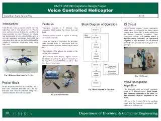
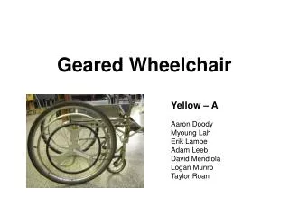
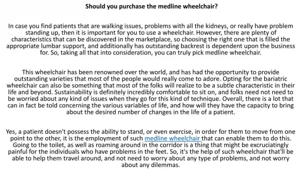
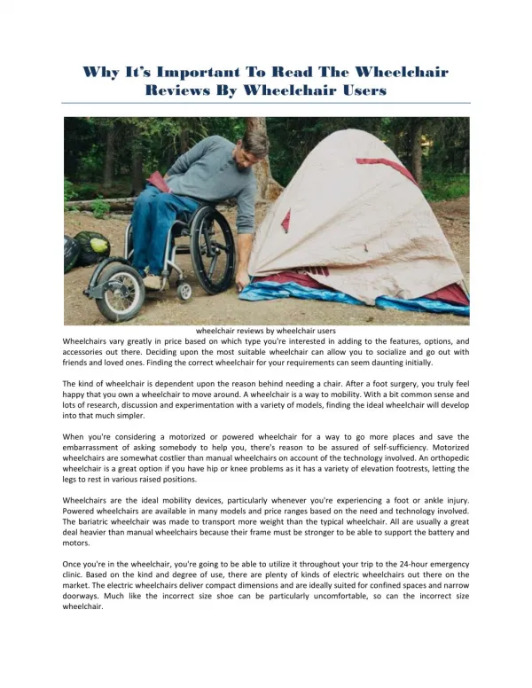
AIM: • The project aims at controlling a wheelchair by means of human voice. • PIC 16F877 is the brain of the control circuit. • The voice recognition is done by HM2007.
DC motors are used to drive the wheelchair. • The driving mechanism used is chain drive. • Two 12V,32Ah maintenance-free, lead acid batteries are used.
DRIVER CIRCUIT RIGHT MOTOR MIC RESET BATTERY CHARGER VOICE RECOGNITION IC MICROCONTROLLER BATTERY SPEED &DIRECTION CONTROL DRIVER CIRCUIT LEFT MOTOR BLOCK DIAGRAM
FEATURES OF HM2007 • It is a 48 pin DIP IC. • Speaker independent mode was used. • Maximum of 40 words can be recognized
Each word can be maximum 1.92sec long. • Microphone can be connected directly to the analog input. • 64K SRAM, two 7 segment displays and their drivers were connected.
PIN DIAGRAM HM6264
TRAINING PROCESS: VOICE TRAINING • Make WAIT pin HIGH for training mode. • Clear the memory by pressing 99 *. • Enter the location number to be trained. • After entering the number the LED will turn off. • Number will be displayed on the display. • Next press # to train.
The chip will now listen to the voice input and LED will turn ON. • Now, speak the word you want to train into the microphone. • The LED should blink momentarily. • This is the sign that the voice has been accepted. • Continue doing this for different words.
VOICE RECOGNITION • Repeat the trained word into the microphone. • If word is rightly recognized, the correct location is displayed. • The error codes are: 55- word too long. 66-word too short. 77-word no match.
PCB- Key Board Component Side Soldering Side
Voice Recognition Circuit on Bread Board • The circuit worked • well on bread board • PCB Design is over. • Soldering remaining
Problems Encountered: • There were many basic mistakes in the the application circuit in the datasheet itself. • The CHIPSELECT of SRAM(PIN26)is an active high input, we tied it to ground through a capacitor and resistor as indicated in the application circuit.
Interfacing of 74LS373 with HM6264-Many Wrong Connections. • Interfacing 74LS47 with 74LS373-Many Wrong connections • One of the common anode 7-segment drivers was damaged.
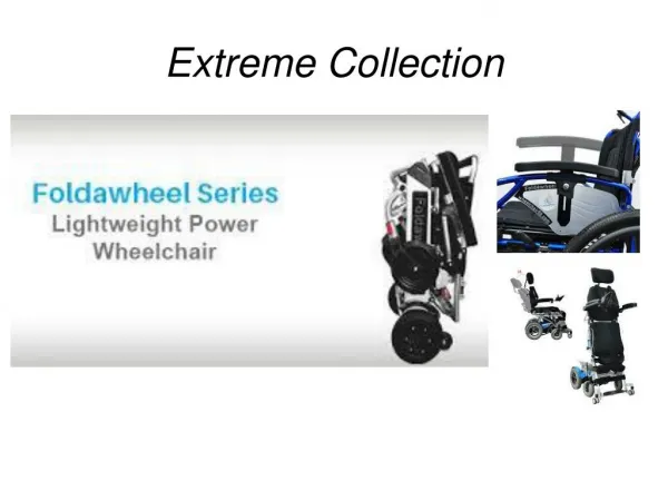
MOTORS AND BATTERIES: • After calculations the following motor specifications were arrived at: 57W, 17.1Nm, 30 rpm. • The motor procured from AGNI MOTOR,BANGLORE has the following specifications:120W,9.8Nm,60 rpm with no load. • Two 12V,32Ah lead acid AMARON batteries were purchased
Power calculations • Trial1- m=40kg s=5.321mt=15ss=ut+0.5at2therefore, a=0.047m/s2 v=0.705m/s • Trial 2- m=40kg s=5.321mt=14ss=ut+0.5at2therefore, a=0.054m/s2 v=0.7601m/s • Trial 3-m=40kg • s=5.321mt=7ss=ut+0.5at2therefore, a=0.21m/s2 • v=1.52m/s
MOTOR CALCULATIONS • R=0.3ma=0.21 m/s2 (maximum possible practically)v (max)=2m/sm=100kg takenF= ma + μN=21+0.04*900=57Nnote:0.02 is the frictional co- efficient for a smooth surface..0.04 is the roughest possible.900N is taken as a std valueP=F*v (max)=114W,both motors….57W one motor……Τ = F* R=57*0.3=17.1Nm To find rpm of motor t=7ss=5.321mv=1.52rpm=(s*60)/(2*3.14*R*t)=26rpm now, s=5.321mv=v (max)=2m/sfrom v2=2as, a=0.375m/s2from, v=at, we get t= 5.5s Therefore, rpm=(s*60)/(2*3.14*R*t)=31rpm finally, each motor should at least be 60W,100rpm
THINGS TO DO: • Programming of PIC16F877 • Motors to be coupled to the wheel chair by chain drive mechanism. • Design of the speed and direction control circuit. • Design of battery charger.