Download
1 / 31
310 likes | 510 Vues
Positive Semantics of Projections in Venn-Euler Diagrams. Joseph Gil – Technion Elena Tulchinsky – Technion. Seminar Structure. Venn-Euler diagrams Case for projections Positive semantics of projections Different approach : negative semantics of projections. Terminology.

E N D
Positive Semantics of Projections in Venn-Euler Diagrams Joseph Gil – Technion Elena Tulchinsky – Technion
Seminar Structure • Venn-Euler diagrams • Case for projections • Positive semantics of projections • Different approach : negative semantics of projections
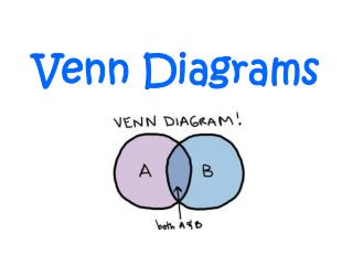
Terminology • contour - simple closed plane curve • district - set of points in the plane enclosed by a contour • region - union, intersection or difference of districts • zone - region having no other region contained within it • shading - denote the empty set • projection, context - another way of showing the intersection of sets
Venn Diagrams B A C • n contours • 2n zones • shading to denote empty set
Venn Diagrams (cont.) The simple and symmetrical Venn diagrams of four and five contours • Venn diagram disadvantages: • Difficult to draw • Most regions take some pondering before it is clear which combination of contours they represent
B A D C Venn-Euler Diagrams • The notation of Venn-Euler diagram is obtained by a relaxation of a demand that all contours in Venn diagrams must intersect • The interpretation of this diagram includes: • D (C - B) - A and ABC = • 9 zones instead of 24=16 in Venn diagram of 4 contours
Women Company Employees Company Employees Women Projections using projections without projections Denoting the set of all women employees • A projection is a contour, which is used to denote an intersection of a set with a context • Dashed iconic representation is used to distinguish projections from other contours • Use of projections potentially reduces the number of zones
Q A A B B A B E C D C C A B A B C B A B A C C C B A C F Case for Projections • A Venn diagram with six contours constructed using More’s algorithm • A Venn diagram with six contours using projections shows the same 64 zones
Queens Kings married Executed Henry VIII Case for Projections in Constraint Diagrams • The sets Kings and Queens are disjoint • The set Kings has an element named Henry VIII • All women that Henry VIII married were queens • There was at least one queen Henry VIII married who was executed • Divides the plane into 5 disjoint areas ( zones )
Queens Kings married Henry VIII Executed Queens Kings married Henry VIII Executed Case for Projections in Constraint Diagrams (cont.) • Executed contour must also intersect the King contour • State that Henry VIII was not executed • Divides the plane into 8 disjoint areas • Using of spider to refrain from stating whether or not Henry VIII was executed • Draws the attention of the reader to irrelevant point
Questions • Context What is the context with which a projection intersects? • Interacting Projections What if two or more projections intersect? • Multi-Projections Can the same set be projected more than once into a diagram? Can these two projections intersect?
C B D A B D B C D Intuitive Context of Projection • Projection into an area defined by multiple contours • D~ = D ( B + C ) • To make the strongest possible constraint we choose the minimal possible context • D~ = D B with B A • Multiple minimal contexts • D~ = D ( B C )
B1 B2 C2 D C1 B E D A D Intuitive Context of Projection (cont.) • Generalization of previous examples • D~ = D ( ( B1 + C1 ) ( B2 + C2 ) ) • Contours disjoint to projection can not take part in the context • D~ = D B • The context of a contour can not comprise of the contour itself • An illegal projection
Mathematical Representation C B z1 z2 z3 Main idea: To define a formal mathematical representation for a diagram • < { B, C }, {z1, z2, z3} > z1 = B - C z2 = B C z3 = C - B z1 = { B } z2 = { B, C } z3 = { C } • Each zone is represented by the set of contours that contain it
A z9 z1 z8 E z7 z2 z4 z6 z5 z3 D B C Example < { A, B, C, D, E }, {z1, z2, z3, z4, z5, z6, z7, z8, z9 } > z1 = { A } z4 = { A, B, D } z7 = { A, B, C } z2 = { A, B } z5 = { A, C, D } z8 = { A, E } z3 = { A, C } z6 = { A, B, C, D } z9 = { E }
Mathematical Representation (cont.) Definition A diagram is a pair < C, Z > of a finite set C of objects, which we will call contours, and a set Z of non-empty subsets of C, which we will call zones, such that c C, z Z, c z. Dually: The districtof a contour c is d ( c ) = { z Z | c z }. The districtof a set of contours S is the union of the districts of its contours d ( S ) = c S d ( c ).
Covering is basically containment of the set of zones Covering Definition We say that X is covered by Y if d ( X ) d ( Y ). We say that X is strictly covered by Y if the set containment in the above is strict. (X and Y can be sets) A cover by a set of contours is reduced, if all “redundant” contours are remove from it Definition A set of contours S is a reduced cover of X if S strictly covers X, X S = , and there is no S’ S such that S’ covers X.
Territory and Context Definition The territory of X is the set of all of its reduced covers ( X ) = { S C | S is a reduced cover of X }. Definition The context of X, ( X ) is the maximal information that can be inferred from what covers it, i.e., its territory ( X ) = S ( X ) d ( S ) = S ( X )c S d ( S ). If on the other hand ( X ) = , we say that X is context free.
Projections Diagram Definition A projections diagram is a diagram < C, Z >, with some set P C of contours which are marked as projections. A projections diagram is legal only if all of its projections have a context.
I H E I U E H Interacting Projections • H~ = H I • E~ = E H~ = E H I • H~ = H ( I + E~ ) • E~ = E ( U + H~ ) H~ = H ( I + E ( U + H~ ) ) = H I + H E U + H E H~ = H~ + = H E = H I + H E U = H ( I + E U )
Solving a Linear Set Equation Lemma Let and be two given sets. Then, the equation x = x + holds if and only if x +; . • The minimal solution must be taken • In the example: H~ = = H ( I + E U ) • E~ = E ( U + H~) = E ( U + H ( I + E U ) = • = E U + E H I + E H U = E ( U + H I )
Dealing with Interacting Projections • Main problem: the context of one projection includes other projections andvice versa. • System of equations: • Unknowns andconstants:sets • Operations: union and intersect,“polynomialequations” • Technique: use Gaussian like elimination
System of Equations x1 = P1 (1, . . . , m, x2, . . . , xn ) . . . xn = Pn (1, . . . , m, x1, . . . , xn-1 ) where x1, . . . , xn are the values of p P ( unknowns ), 1, . . . , m are the values of c C ( constants ), P1, . . . , Pn are multivariate positive set polynomial over 1, . . . , m and x1, . . . , xn. Lemma Every multivariate set polynomial P over variables 1, . . . , k, x can be rewritten in a “linear” form P ( 1, . . . , k, x ) = P1 ( 1, . . . , k ) x + P2 (1, . . . , k ).
Procedure for Interacting Projections • Solve the first equation for the first variable • Solution is in term of the other variables • Substitute the solution into the remaining equations • Repeat until the solution is free of projections • Substitute into all other solutions • Repeat until all the solutions are free of projections
B C D D f g B C D D g f Multi-Projections • Df = D B • Dg = D C • Df = D B • Dg = D C • D B C =
B C D D f g Noncontiguous Contours • Problem • Main idea: unify the multi-projections • Instead of having multiple projections of the same set, we will allow the projection to be a noncontiguous contour • The mathematical representation does not know that contours are noncontiguous • Only the layout is noncontiguous. • Df = D B • Dg = D ( B C ) • = Df Dg = D B C = Dg
E z8 A z9 z8 D D E D z5 z4 z6 z9 z7 E z2 z3 B C z1 Noncontiguous Layout • May have noncontiguous contours and noncontiguous zones
Noncontiguous Projection B C D D • D~ = D B • The interpretation of this diagram does not include: = Df Dg
Summary • Context:the collection of minimal reduced covers • Semantics: computed by the intersection with the context • Interaction: solve a system of set equations • Multi-projections: basically a matter of layout
Related Work • Negative semantics: compute the semantics of a projection based also on the contours it does not intersect with. (Gil, Howse, Kent, Taylor) • Different approach. Not clear which is more intuitive
Difference between Positive and Negative Semantics B D E • Positive Semantics : D~ = D B D~ E = • Negative Semantics : D~ = D ( B - E )