Download
1 / 26
260 likes | 363 Vues
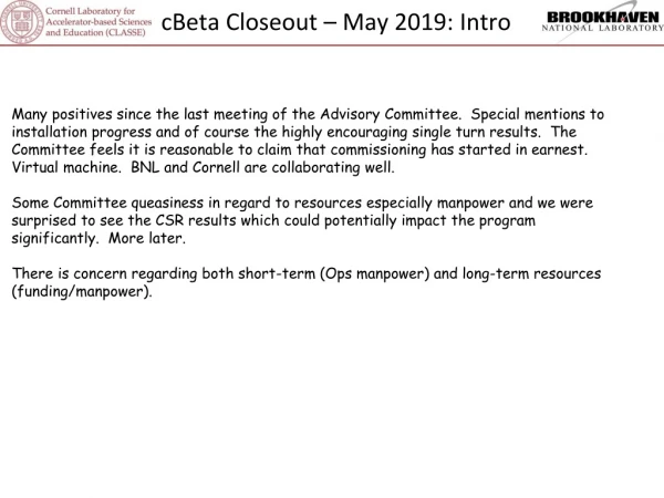
This overview covers the RF hardware and cryogenic systems of CBETA, including challenges faced since 2018 and solutions implemented for optimal performance.

E N D
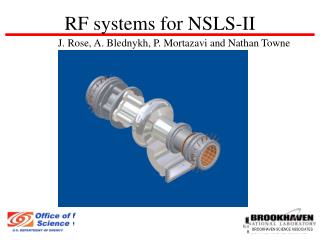
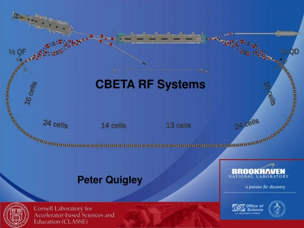
CBETA RF Systems Peter Quigley
CBETA RF Systems: Overview • RF Hardware • Cryogenic Systems • Warmup/Cooldown • Tuning • RF Control • Future Plans
CBETA RF Systems: RF Hardware Injector Cryomodule (ICM) Twin Input Power Coupler HGRP with three sections Support Posts 300K to 2K Isolation HOM load at 80K between cavities µ-metal “Lunch Box” around cavities WPM, (one on each cavity) 1.3 GHz 2-cell SRF cavity, blade tuner. Wire Position Monitor (WPM) tube
CBETA RF Systems: RF Hardware Main LINAC Cryomodule (MLC) Helium Gas Return Pipe (1 section) Input Power Coupler (Max 10 kW) • 6 7-cell Cavities • ΔE = 6 MeV • σA/A ~ 10-4, σφ~ 0.1° 2K 2-Phase Helium Line • Based on TESLA cryomodule design with important differences: • Optimized for CW operation. • Designed for ERLs. • Cavities hang from the HGRP which is used to align them. 7 HOM Absorbers (Max 400 W)
Stiffening Rings Stiffened Cavity CBETA RF Systems: RF Hardware Main LINAC Cryomodule (MLC), Input Coupler, Tuner, Solid State Amplifiers (SSA) 3- Stub WG Tuner 2K Tuner Motor SSAs RF Power Isolators Piezo Tuner 5 kW Slow Cavity Tuner 10 kW Unstiffened Cavity 5 kW 10 kW 5 kW 10 kW Input Power Coupler Waveguide Flange • Status: • MLC is currently at 1.2 K (12.5 TorrHelium Pressure). • Vacuum: • Insulation: 8.0x10⁻⁶ Torr • Cavity Beamline: 1.8x10⁻¹¹ Torr • Input Power Couplers: 6.0x10⁻¹⁰ Torr (average of six couplers) Warm Ceramic Window 300K Flange 40K Flange and cooling Air Cooling Bellows Cavity Flange (1.8) Pump Port Cold Ceramic Window Instrumentation Port Antenna 5K Intercept
CBETA RF Systems: RF Hardware What Happened Since 2018 AC • ICM • Klystron #3 needed solenoid current adjustment. • ICM delivers 6 MeV reliably. • MLC • SSA firmware upgrade: 1/20/2019. • SSA power up with shorted waveguide and interlocks bypassed. • Tuned cavities with network analyzer. Motors are vulnerable. • CM2, SECOND 1.3 GHZ CRYOMODULE FABRICATION AT FERMILAB* T. Arkan, PAC2013 • Connected RF power to cavities, all initially tested for operation at 6 MeV, no issues.
CBETA RF Systems: RF Hardware What Happened Since 2018 AC • MLC (continued) • SSA operating condition • Firmware update introduced new bug. • External interlock trip requires AC power cycle to reset. • Put external interlocks in series with PPS. Works well enough. • Working with manufacturer to resolve. • SSA #6 48 VDC power supply interlock false failure indication. • Measurements show power supply is working. • Interlock is bypassed. Checking with manufacturer to see if operating in this state is ok. • Ordering spare supply
CBETA RF Systems: MLC SSA Test After RF Power Circulator Repair All isolators were repaired: (Slide From October 2018 AC) Tuning screws were removed and the resistive load were disassembled. Broken ferrite tiles were removed and the load surface was cleaned. Plastic residue was blown out with dry nitrogen. The isolator was reassembled and the tuning screws were adjusted to optimize isolation using a network analyzer. All SSAs and isolators were tested to full power CW! Loads damaged due to arcing triggered by damaged plastic on tuning screws. Damage to load surface on 5 kW loads Ferrite damage on 10 kW loads
Port 2 Arc Detector Port Port 3 Tuning Screws CBETA RF Systems: RF HardwareRF Power Circulators • RF Power Circulators • AFT refuses to warranty RF power circulator damage. • Concern is water leak on cooling plate in pitted locations. • Adding automatic valve for cooling water ON/OFF. • Agreed to fix at factory but confidence in a timely turn around is low. • Requesting that AFT send new ferrite plates for repairs to be done at Cornell. Water Cooled Ferrite Load Inside Tapered Waveguide Port 1 • Isolators tuning screw insulator disintegrated on the initial test depositing a power-like substance on the interior surface. • No Arcing detected at any time during RF operations. Damaged New
CBETA RF Systems:Cryogenics • Cryogenic Systems: • Added sleeves to all MLC cryogenic valves (microphonicssuppression). • Modified MLC cryogenic pumping lines to mitigate oil flow between skids. • Checking microphonics impact when using different pump skids. • 2K 2-Phase Helium Level Control: • RF OFF: JT regulates helium level. • RF ON: Either 2K 2-Phase heater or the JT regulates helium level. • Working on optimizing both.
CBETA RF Systems:Warmup/ Cooldown • Warmup/Cooldown: • ICM • Idle at 80K since 6/14/2018 through 2/28/2019. • Cooldown to 2K 3/4/2019, no issues. • MLC • (Warmed to room temperature 5/23/2018.) • MLC Beamline height correction: 3/4/2019 • Beam based measurements show beam line is ~4 mm too high. • Survey could only account for 2 mm offset. • Beamline thermal shrinkage ~1 mm. • Lowered MLC vacuum vessel 2mm, beamline 1.2mm (Next Slide).
CBETA RF Systems: MLC Vertical Offset • Beam based measurements show beam line is ~4 mm too high. • Survey could only account for 2 mm offset. • Beamline thermal shrinkage ~1 mm • Lowered MLC vacuum vessel 2mm, beamline 1.2mm • Thermal shrinkage is ~1.2 mm. Not accounted for during MLC assembly. Two room temperature height adjustment screws on each support post. • Survey shows ~ 1mm error on the BPM position. Lowered MLC vacuum vessel 2mm BPM just downstream of the MLC exit flange. MLC Support Stand
CBETA RF Systems:Cavity Tuning • Tuning • ICM Cavity #2 cannot be tuned to 1299.9 MHz, detuned, Klystron HV disconnected. • MLC cavity #6 mechanical tuner limit forces the CBETA operating frequency to be 1299.9 MHz. • This tuner is not easily accessible in-situ. Risky, Time consuming.
CBETA RF Systems:Cavity Tuning • ICM • Cavities require occasional tuning otherwise operation is reliable. • Field stability is optimized • MLC • Microphonics and LDF compensation is working well.
CBETA RF Systems:RF Control • RF Control • MLC cavity field stability. • Measured noise/crosstalk on LLRF cavity field signal. • ICM ~1 kV rms. • MLC ~10 kV rms. • Likely source being on the RF high power side. • Waveguide is a likely source. • Flanges. • Directional couplers. • RF leak checking on the schedule. • Cavity #5 is not operating in klystron or cavity loop. • Investigating.
MLC Microphonics Slight increase in peak microphonics detuning on most cavities, but we are still within our RF power budget for 36 MeV operations. Slide By Nilanjan Banerjee
CBETA RF Systems:Future Plans • RF • Continue to optimize loop parameters as conditions require. • Measure and characterize RF noise/vibration sources • Mechanical • New vibration sources added since FAT. • Added additional cryogenic valve sleeves. • Cause return of the 41 Hz vibration? • Cooling ventilation duct work. • Cooling water systems. • New equipment platform. • New cable tray and conduits. • Clamp waveguides with Sorbothan. • Decouple SSA waveguide from Klystron mezzanine. • Measure 2K Helium pumping line vibrations, (using different skids). • Electrical: • Locate and isolate RF leaks. • Shield electronics if necessary. • Check for ground currents/loops. • A fair amount of ground connections were made according to electrical code requirements. • Cryogenics • Continue to optimize loop parameters as operating conditions require. • Automating Skid bypass control valves.
CBETA RF Systems:Conclusion • CBETA RF Systems have delivered up to 59 MeV energy gain, (during FAT) and can reliably deliver 42 MeV. • CBETA RF system Team continues to work system optimization and address issues both current and as they arise.
Port 2 Arc Detector Port Port 3 CBETA RF Systems: MLC Solid State Amplifier (SSA) Initial Test Tuning Screws Water Cooled Ferrite Load Inside Tapered Waveguide Port 1 • Isolators tuning screw insulator disintegrated on the initial test depositing a power-like substance on the interior surface. SSA Test Setup Isolator (AFT) • No Arcing detected at any time during RF operations. Directional Coupler SSA (SigmaPhi) Damaged 3 Stub Tuner New Short install at waveguide output (Slide From October 2018 AC) Circulating Ferrites
Port 2 Arc Detector Port Port 3 CBETA RF Systems: MLC SSA Test After Isolator Repairs Tuning Screws Temperature monitored at this location Water Cooled Ferrite Load Inside Tapered Waveguide Port 1 AFT Isolator tuning screw temperature during high power test following tuning screw insulator replacement. Tests were not simultaneous and duration of tests varied for arbitrary reasons. (Slide From October 2018 AC)
Energy Scan The MLC successfully reached an energy gain of 53.2 MeV during operations. Total Energy Gain (6 MeV from ICM) SSA Isolator Temperature 30 • Isolator screw temperatures were below 30 C at all times! • Peak blower speed was 67.5% for both skids. 29 Kelvins 28 Exceeded design energy gain by 50%! 27 (Slide From October 2018 AC) 26 -5 22:45:16 May 18, 2018 -20 -15 -10 Time (Hours)
CBETA RF Systems:MLC Tuning • Tuner assembly mounted on unstiffened cavity.
Waveguide motion showing effect of striking the structure in the “wrong” spot. • I made the mistake of striking the waveguide at point 2 which made it look like the second waveguide from the left was more sensitive than all of the rest. • I should have struck it on the insulating vessel at one end of in the center in order to excite all of the waveguides about the same. • Even still we got the information that we needed as this design had a beam between all of the waveguides and we found a 20 Hz mode of that structure which would have been “amplified” to the 21 Hz half string mode when it got to the cavities. Slide By Tom Powers, LLRF Microphonics Workshop Oct. 2018