Download
1 / 19
190 likes | 213 Vues
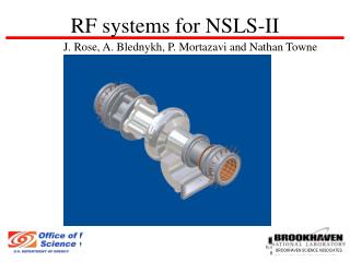
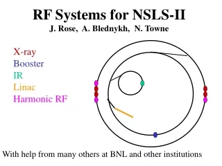
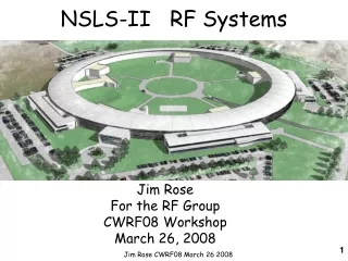
NSLS-II RF Systems. Jim Rose For the RF Group CWRF08 Workshop March 26, 2008. Outline. NSLS-II design approach RF specifications derived from user beam RF baseline design and options Booster RF baseline and options Window of opportunity for choices and strategic planning.

E N D
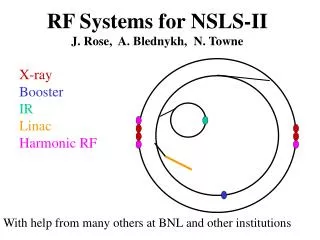
NSLS-II RF Systems Jim Rose For the RF Group CWRF08 Workshop March 26, 2008 Jim Rose CWRF08 March 26 2008
Outline • NSLS-II design approach • RF specifications derived from user beam • RF baseline design and options • Booster RF baseline and options • Window of opportunity for choices and strategic planning Jim Rose CWRF08 March 26 2008
NSLS-II Parameters Jim Rose CWRF08 March 26 2008
NSLS-II Design Approach • Large circumference of 792m (soft bends) for low natural emittance, ε0 = 2.1 nm • 54 m of 1.8 T damping wigglers in zero dispersion straights to further reduce emmitance to ~0.5nm. Only 21 m of DW and ~1/4 RF power installed day one due to cost constraints Jim Rose CWRF08 March 26 2008
RF Phase, Energy Stability Requirements Guo et al, PAC 2007 Jim Rose CWRF08 March 26 2008
Ring RF Landau Cavity • A harmonic bunch-lengthening cavity is required to increase Touschek lifetime. Without bunch lengthening lifetime is ~2 hours • Increases beam stability by increasing energy-dependent tune spread • Baseline is to use the passive Super3HC cavity*. • Proven design at SLS, ELETTRA • Two cells per cavity delivering 1MV well matched to ring requirements and upgrade path * If available Jim Rose CWRF08 March 26 2008
Illustrative bunch profiles Four Gaps One Gap Two Gaps Bunch lengths and phase offsets along train Breaking up the gap lessens the transient due to both a shorter gap and shorter interval between the gaps. N. Towne Jim Rose CWRF08 March 26 2008
Limit in bunch lengthening due to ion gap transients induced phase offset along bunch trains SCRF case. One gap (red) two gaps (green) four gaps (blue) Nathan Towne NCRF Case Jim Rose CWRF08 March 26 2008
RF System Design Concept/Design Goal Ring RF system • CESR-B SCRF cavities chosen for ring RF • low impedance better for beam stability • higher AC power efficiency • Reliability and costs well established • KEK-B SCRF cavity as option • Keep second vendor • minimal impact on conceptual design • Requires more BNL infrastructure to assemble, test • 310 kW Klystron amplifiers chosen for baseline: • Well established at other LS facilities • Reliability and costs well established • Combined IOT’s as option, possible R&D on Solid State amplifiers • Passive SCRF Landau cavity • Super3HC Demonstrated performance at SLS, ELLETRA • Beampipe HOM damped design being explored Jim Rose CWRF08 March 26 2008
NSLS-II RF VOLTAGE, POWER REQUIREMENTS Jim Rose CWRF08 March 26 2008
RF Straight with 2 CESR, 1 Landau Cavity CESR-B cavities operating in TLS, CLS, Diamond, Shanghai Mature Technology Jim Rose CWRF08 March 26 2008
Landau: alternate cavity design Two cavities per cryomodule to save length Initial results encouraging Possible SBIR with Niowave (NSCC/Michigan spinoff) Jim Rose CWRF08 March 26 2008
Klystron RF Feedback Loop • Klystron RF stability vs. DC supply: • RF phase variation vs. beam voltage (constant mod. Anode voltage) 12 degrees/% • RF power vs. beam voltage 0.2dB/% • PSM power supply typical performance (54kV,12A) • Full range < 1% pk-pk • 75V from 1kHz-2kHz (0.1%) = 1.2 degrees • 15V from 2kHz-4kHz • 3V from 4kHz-12kHz • 50V for >12kHz This is limiting factor at other facilities, ~1 degree phase jitter after feedback using mod-anode Need Feedback! Local “scalar” feedback around klystron + global RF feedback Jim Rose CWRF08 March 26 2008
Booster RF System Requirements • Booster energy: 200MeV 3 GeV • RF frequency: 500 MHz • Repetition rate: 1 Hz RF voltage ramp • Average beam current: 19 mA (10 nC circulating charge) Energy loss per turn: 625 keV Beam power: 11.8 kW ● Energy acceptance: 0.85% at 3 GeV 1.5 MV booster RF voltage • Use a multi-cell cavity with reasonably high shuntimpedance, e.g. PETRA type cavities RF bucket at 3 GeV ALBA BESSY CLS DIAMOND Jim Rose CWRF08 March 26 2008
Booster Cavity Options and Power Requirements Jim Rose CWRF08 March 26 2008
Booster: IOT Tube transmitter • Well established technology, several tube manufacturers • (CPI, EEV, Thales, Litton) • Turn key transmitters are available incl. all internal safety • and interlock circuits • IOT upgrade program goal: 100 kW output, improved reliability • → increase output coaxial window to 6-1/ • → use larger ceramic (compatible with old socket) Jim Rose CWRF08 March 26 2008
Opportunities and Strategic planning • NSLS-II storage ring RF systems are staged over many years to keep pace with additional damping wigglers, user ID’s • First system purchased in ~January 2010, 2nd possibly before end of project-3rd, 4th beyond 2015. • Choice of klystron or combined IOT’s in near term, solid state for future systems • Hope to answer questions of technical performance (linearity, phase noise), reliability and cost here at this workshop and over the next ~6 months • SS reliability, linearity benefit SR, but like Soleil and SLS, NSLS-II may target Booster to gain experience • Booster requirements well matched to IOT, would not target booster without SR as strategic goal. Jim Rose CWRF08 March 26 2008
Motivation for Solid State Amplifier R&D Solid state amplifier R&D program proposed • Elimination of high voltage, no vacuum tube replacement, no crow bar circuit • Graceful degradation in case of module failures (failure rate ~ 3% / year including infant mortality) • Linear operation avoids saturation: • simplifies design of rf feedback loops • ● Present investment cost estimates 30-50% higher than IOT transmitter, potential for future cost reduction • → Potential for higher system reliability • → Significant saving in maintenance costs (?) • Mean time between failure? • Lower mean time to repair MTTR? 45 kW 352 MHz solid state transmitter at SOLEIL with 181 modules Jim Rose CWRF08 March 26 2008
Acknowledgements Credits to Nathan Towne,,Sam Krinsky, Hengjie Ma, Timur Shaftan, Steve Kramer, Alexei Blednyk, Weiming Guo, Satoshi Ozaki and Ferdinand Willeke from NSLS-II Special thanks to Hasan Padamsee, Sergy Belomestnykh and Valery Shemelin at Cornell, T. Furuya at KEK, Mark deJong at CLS and Chaoen Wang, P. Chou at NSRRC, Ernst Weihreter at Bessy, Ali Nassari, Doug Horan at APS, Patrick Marchand and T. Ruan at Soleil, Marcos Gaspar and Marco Pedrozzi at SLS, Eric Marguto and Jim McVea at Thales, Steve Lenci at CPI, Juergen Alex and Henry Fries at Thomson Jim Rose CWRF08 March 26 2008