Download
1 / 31
310 likes | 503 Vues
NSLS II: Accelerator System Overview NSLS II Accelerator Systems Advisory Committee October 10, 2006 Satoshi Ozaki. Introduction. NSLS II: A highly optimized, third generation, medium energy storage ring for the x-ray synchrotron radiation:

E N D
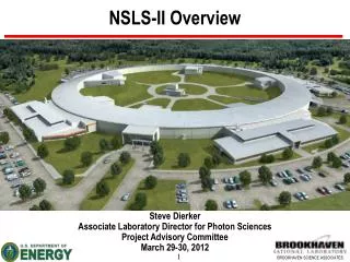
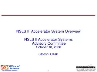
NSLS II: Accelerator System Overview NSLS II Accelerator Systems Advisory Committee October 10, 2006 Satoshi Ozaki
Introduction • NSLS II: A highly optimized, third generation, medium energy storage ring for the x-ray synchrotron radiation: • The CD-0 approval articulated required capabilities as: • ~ 1 nm spatial resolution, • ~ 0.1 meV energy resolution, and • single atom sensitivity (or sufficiently high brightness). • These requirements translate into the target parameters of the storage ring as; • ~3 GeV, 500 mA, top-up injection • Brightness ~ 7x10²¹ photons/sec/0.1%bw/mm2/mrad2 • Flux ~ 1016 photons/sec/0.1%bw • Ultra-low emittance (x, y): 1 nm horizontal, ~0.01 nm vertical • 20 straight sections for insertion devices ( 5 m), • A high level of reliability and stability of operation.
Steps in the Baseline Configuration Development • The original lattice for CD0 proposal was TBA24 with tight bend and 630 meter circumference. • Although the desired small emittance (x~1.5 nm) was thought to be within reach with the perfect lattice, it was found that any reasonable errors would have closed up the dynamic aperture. • Search of an alternative: • Enlarged TBA24 lattice • DBA lattice with more straights for damping wigglers for emittance control. • Weak bends to enhance damping by wigglers. • CD0 proposal also included a full energy linac injector. • A booster in the storage ring tunnel was chosen for this baseline configuration with due consideration of reliability, performance and cost.
The Preliminary Review of NSLS II Lattice and Accelerator Configuration: May 11-12, 2006 The Committee : • Dr. Carlo Bocchetta, Sincrotrone Trieste • Dr. Michael Boege, Swiss Light Source • Dr. Michael Borland, Argonne National Laboratory • Dr. Max Cornacchia, Stanford Linear Accelerator Center (retired), Chairman • Dr. Mikael Eriksson, MAXLAB • Dr. Thomas Roser, Brookhaven National Laboratory • Dr. Christoph Steier, Lawrence Berkeley National Laboratory The approach of NSLS II is to achieve the performance goal • with a lattice whose focussing strength is comparable to that of existing 3-rd generation sources, but that also includes a number of damping wigglers to further reduce the emittance without the deleterious effect on the dynamic aperture normally associated with strong focussing lattices. • Thus, the proposed design includes innovative ideas for a light source (damping wigglers and soft bends), informed by the experience of state-of-the-art existing facilities. • While the design presents challenges for the beam dynamics, beam instrumentation, controls and hardware, the performance goals appear achievable.
DBA 30 and Its Expected Performances • 3 GeV, 500 mA, top-up injection • Fifteen Superperiod consisting of two identical cells • Fifteen 8-m long straights and 15 5-m long straights • min,x /min,y @ 8-m straight = 18.2 m/3.1 m (Hi-) • min,x /min,y @ 5-m straight = 2.7 m/0.95 m (Lo-) • Bare Lattice: x ~2.1 nm, y ~0.008 nm (Diffraction limited at 12 keV) • Pulse Length (rms): 2.9 mm/~10 psec • Ultimate performance with full complement (56m 1.8T) of wigglers • Emittance (x, y): ~0.5, ~0.008 nm • Flux ~ 1016 photons/sec/0.1%bw • Brightness ~ 7x10²¹ photons/sec/0.1%bw/mm2/mrad2 • 19 user device (e.g., undulators) straights (15 x 5 m & 4 x 8 m) • 5 user compatible (fixed gap) damping wigglers • Beam Size (x/ y) at the center of short straights: ~38.5/~3.1 m • Beam Divergence (x’/y’) ~18.2/~1.8 rad • Pulse Length (rms) with damping wigglers: 4.5 mm/~15 psec • Ultimate total power loss by bending magnets and insertion devices: ~1 MW • Initial scope and performance is reduced to fit in the budget constraint, while maintaining the upgrade path.
Booster Storage Ring Linac Accelerator System Configuration Booster Booster injection was chosen for a high level of reliability Since we operate with top-up mode, having the booster in the same tunnel will have little impact on the operational reliability
Injector Linac • S-band linac system providing 200 MeV electron beams of 7 nC to the Booster in one pulse • Electron source: thermionic DC gun modulated to match 500 MHz RF of booster and storage ring • The system commercially available in turn-key procurement: • ACCEL • THALES • Issue: control of energy droop causes by beam loading
Booster Synchrotron • 200 MeV to 3 GeV booster • Hung below the ceiling of the storage ring tunnel and has the same circumference of 780 m • Relatively light weight small magnets; low power and air cooled: • 60 combined function dipoles: 1.5 m long, 25 mm gap, 0.7 T, ~580 kg • 96 quadrupoles: 0.3 m long, <10T/m, ~45 kg • 15 sextupoles: 0.4 m long, <200T/m2, ~55 kg • 15 sextupoles: 0.2 m long, <200T/m2,~30 kg • 60 orbit correctors • Up to 100 bunches per cycle for initial fill • Up to 20 bunches per cycle with the hunt and fill bunch pattern • One PETRA-type (commercially available) RF cavity • Very low emittance at the storage injection energy helps smooth low loss top-up injection. • Procure components, build, and commission in-house • Options: turn-key procurement of this booster or a compact booster in separate tunnel • Detailed discussion on Injection system by Timur Shaftan on the second day.
Storage Ring Lattice Layout Linac RF Station
Storage Ring • DBA30 lattice with 15 super-periods, each ~52m long, and 780m circumference • Super-period: two identical cell separated by alternating ~5m and ~8m straights • Weak bends (0.4T) with damping wigglers to achieve ultra-small emittance (~0.5 nm with 56 m of 1.8T wigglers) • Short straight: x = 2.7m, y = 0.95m, and dispersion = zero • Long straight: x = 18.2m, y = 3.1m, and dispersion = zero • This Hi-Lo is suited for variety of ID as well as top-off injection • Utilization of straights and bending magnets • 1 long straight for injection with 4 kicker magnets • 2 long straights for fundamental and harmonic RF cavities • Up to 8 long straights for damping wigglers in the ultimate configuration • Five of them with fixed gap, being suitable for user beamlines • 4 long straights for user insertion devices. • 15 Short straight for user undulators, some with canting • A number of bending magnet for soft X-ray beam lines (critical energy ~2.4 keV) • Several bending magnets for IR, far-IR, and THz beamlines • Variable gap wigglers to compensate the change of undulator setting by users
Lattice functions of half of an NSLS-II SR super-period (one cell).
Dispersion Section of a Cell Alignment tolerance of multipoles on a girder is 30 m, whereas girder-to-girder tolerance is ~100 m In order to reduce the transmission of ground vibrations beam height is set at 1 m from the SR tunnel floor, instead of standard 1.4 m. Girder Resonant Frequency > 50 Hz
Dynamic Aperture of the Lattice For on momentum and off momentum cases by 3%
Horizontal Emittance vs. Energy Radiated by DW Dots represent the cases with 0, 1, 2, 3, 5, 8 damping wigglers, each 7-m long with 1.8 T field
RF Power Up-grade Path RF Power Requirements for Dipole and Various Insertion Device Configurations.
Features of the Storage Ring Design • A large circumference DBA for small bare lattice emittance (~2.1 nm) • The design of the facility mostly depends on the well established technology at other storage ring light sources • Alternate Hi-Lo straights accommodate various requirement for injection, RF, and long damping wigglers for machine, and insertion devices for users • The weak bend combined with damping wiggler reduces the horizontal emittance to sub nm level horizontal • Robust dynamic aperture (~20 mm) and wide momentum acceptance (3%) • 24 straights for the hard x-ray beam from insertion devices • A number of dipoles can be used for soft x-ray and IR beams • The level of RF power can be adjust according to the development of the facility with additional insertion devices and damping wigglers • Booster injection for better reliability • 1 meter beam height and good temperature control for better stability • Extensive array of diagnostic devices for better control of the beam
Issues for Further Studies • Development of precision alignment (~30 µm) technology • Development of the optimum orbit correction and feedback scheme for high level of orbit stability: • A factor of ~3 improvement over the submicron stability recently reported with some recent light sources. • Impact and remediation of 5 mm gap undulator with short pitch to the dynamic aperture and the beam life-time • Because of the vertical focusing effect of undulators with short pitch, they cannot occupy the part of the ID straight where the vertical -function is large, i.e., areas away from the center of the straight. • This limits the 5 mm gap undulator length to ~3 m. • Impact of EPU on dynamics of the beam • Use of canted insertion device • Overall value engineering efforts
Current Baseline Scope/Specifications • Linac: • 200 MeV S-band linac • Turn key procurement • Linac to booster transfer line with spectrometer arm • Booster: • Air cooled magnet ring, 780 m circumference • Full complement of magnets, powered in series, designed with 20% head-room • Power supply rated for 1 Hz operation • PETRA-type 500 MHz room temperature 5 cell RF cavity • In house design, procurement, construction, and commissioning • Booster to storage ring transport line
Current Baseline Scope/Specifications (Continue) • Storage Ring: • Water cooled storage ring, 780 m circumference • All dipole magnets with 60 mm (instead of 35 mm) for IR beam extraction • Dipoles powered in series by one power supply and multipoles and correctors by individual power supplies. • Full complement of magnets designed to allow 20% head room • Extruded aluminum vacuum chambers a la APS • Front end for damping wiggler that will accommodate high power density radiation • Scope of user insertion devices not defined, subject to the user community’s proposal. Funds for devices and beamline front end set aside as trust funds • Initial complement of damping wigglers are to be 2 7 m fixed gap and 1 7 m variable gap. However, only one of each type with 1/3 of length are budgeted. • Two 500 MHz superconducting RF cavities, CESR-B or KEK B type, with power source and a passive 2-cell harmonic cavity will be installed. One spare cavity without power source will be purchased • One refrigerator with ~700W at 4.5K will be procured (turn-key) for the RF system • Procurement of full complement of diagnostic instrumentation is included in the scope • For control system, EPICS architecture has been adopted for now, subject to change
Accelerator System Division Organization Began working on development of baseline configuration in January 2006 ~42 people from NSLS, C-AD, SMD: many of them on part-time base. Effective FTE for this period: ~16.5 Many people from other laboratories (APS, ALS, MIT Bates) provided help The organization anticipated for the construction effort: Accelerator Systems Division Director Deputy Director Accelerator Physics Group Injector System Sub-Project Mechanical Engineering Group* *: also support beamline efforts Storage Ring System Sub-Project Electrical Engineering Group* RF Group Insertion Devices Group Diagnostic & Controls Group
Synopsis of Accelerator Systems Presentations • X-ray Storage Ring V. Litvinenko • NonlinearDynamics, Tolerances, & Dynamic and Momentum Aperture J. Bengtsson • Beam Based Alignment, Beam Stability, Orbit Corrections, and Fast Feed-back S. Kramer • Collective Effects S. Krinsky • Mechanical Sub-Systems S. Sharma • Magnet Power Supplies G. Ganetis • Storage Ring Vacuum System H-C Hseuh • Storage Ring RF System J. Rose • Insertion Devices T. Tanabe • Injection System: Top-up Injection Scheme, Linac, Booster, and Beam Transfer Lines T. Shaftan Not covered: • Beam Line Front-End: Follow experience at APS. As of now, details are not defined, waiting for the determination of the suit of beamlines. • Control System: EPICS was chosen as the backbone for now, but other systems are being studied • Diagnostics: Combination of standard instrumentation is planned.
Summary • Made good progress in last nine months in developing CDR for NSLS II • Optimized and define the configuration of the accelerator systems • Undertook conceptual, in some case more detailed, design of accelerator systems • Assembled accelerator parameter tables • We have a innovative design of highly optimized synchrotron light source capable of meeting requirement articulated in CD-0 document with ultra-high performances • There are a number of issues requiring further study:. • Insertion devices and their impact on the dynamic aperture and beam life-time • Diagnostics and feed-back for the required highly stable beam operation • General value engineering exercise to control costs

![First birds’ fly Institute City, Country Name distance [Km] Accelerator](https://cdn2.slideserve.com/4143004/slide1-dt.jpg)