Download
1 / 14
140 likes | 318 Vues
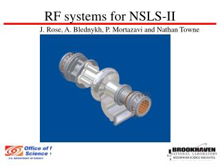
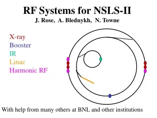
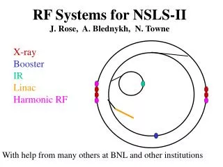
RF Systems for NSLS-II J. Rose, A. Blednykh, N. Towne. X-ray Booster IR Linac Harmonic RF. With help from many others at BNL and other institutions. X-RAY Ring RF requirements. Beam energy gain/cav. >2.4 MV. Eacc. >8 MV/m. Unloaded Q. >7 10 8. Frequency. 500 MHz.

E N D
RF Systems for NSLS-IIJ. Rose, A. Blednykh, N. Towne X-ray Booster IR Linac Harmonic RF With help from many others at BNL and other institutions
Beam energy gain/cav >2.4 MV Eacc >8 MV/m Unloaded Q >7108 Frequency 500 MHz Standby (static) losses <30 W Dynamic + static losses <120W Operating Temperature 4.5 K Max. beam power/cavity <250 kW Baseline CESR-B Cavity SCRF chosen for lower R/Q, highly damped HOM’s, lower operating cost and comparable capital cost CESR-B has well established commercial production. Units 15 and 16 now being produced by ACCEL. In operations at Cornell (4), CLS(2), Taiwan (2). Being commissioned at Diamond (3). Ordered for ASP(?)
1500MHz “Bessy” cavity Voltage/cavity 0.5 MV Eacc >5MV/m Unloaded Q >7108 Static losses <6W Dynamic + static losses <12W Operating T. 4.5 K Frequency 1500 MHz Harmonic Cavity for Bunch Lengthening 4.9MV @500MHz required for 3% Momentum acceptance: 1.6MV @ 1500MHz requires 3 cavities Work continues on effect of bunch train transients on bunch lengthening N. Towne
X-Ray Ring Layout • 4 - 500 MHz cavities • (1MW req’d and 250kW/coupler) • 3- 1500 MHz cavities • (4.5MV @500MHz=1.5MV At 1500MHz and 0.5MV/cav) Stray magnetic fields at cavities must be << 0.5 Gauss at cooldown !
IR Ring Requirements Vacc >2.5MV Beam current =1.0A (1.5) Beam power <10 kW Fwd. and Rev. Power vs. I 1 SCRF module (1M$ cavity, 0.2M$ RF + >120W @4.5k cryoplant) Low beam power means either matching stubs or adjustable coupling Benefits from Antennae Coupler !
RF Power Source Options • Thales 310kW transmitter • costed, one per cavity • @ 2.3M$ ea • CPI 800 kW klystron exists • if dual or high power coupler • adopted (can be optimized for 600kW) • Option: Combine 50 kW IOT’s from broadcast industry (times 6 or 12 does not seem attractive,will study Diamond’s results) • Will use IOT’s for Booster, IR ring TH2161B installed at CLS
Energy loss per turn = 1MeV, Vacc = 2MeV for 0.9% RF acceptance Negligible Energy gain per turn ~29 keV for 300ms ramp Beam current = ~3mA (~6mA for IR) Beam power 3-6 kW Booster RingRequirements 2 “Petra” type cavities and 2 -50kW IOT’s (1.5M$ cavities + 0.4M$ RF) OR 1 SCRF module + 1 -50kW IOT (1M$ cavity, 0.2M$ RF + >92W @4.5k cryoplant)
Cavity Modeling with GdFdl Alexei Blednykh GdfidL vs. CFISH Benchmark ferrite losses, superconductor surface resistance GdfidL vs. measurements Confirm ferrite properties Full Cavity results are now being calculated to be used to analyze CB instability Next is coupler analysis, Cavity pair with spool piece
MOTIVATION Reduces # X-ray cavities from 4 >2 which reduces ring impedance Adjustable coupling to minimize IR ring, Booster rf power req’d. Lower static cryo-losses Frees up 6m straight ! R&D roadmap for power coupler • R&D needs: • RF transmitter • Coupler development • Coupler test stand • Cryo-test facility • Cavity prototype • FOR NSLS-II: Dual antennae coupler design most appealing ! • 250kW/coupler has been demonstrated, 500kW/cavity low technical • risk. • Adjustable coupling allows better matching for low power • requirements of Booster, IR rings: need only one coupler: lower cost • Road to upgrade: Add HOM to IR ring 2nd coupler port?
Cryo-Plant Requirements * Not sure how many VB’s needed, how many meters of transfer line
Frequency 2.9983 GHz • Length 5.2 m • Shunt imp. 51 MW/m • Q 14000 • Filling time 0.74 ms • Energy gain 12.6*sqrt(PMW ) • Attenuation = 0.55 Np 2.998 GHz Linac Picture courtesy of ACCEL Energy gain 80MeV/tank for 40MW power input (no-load) 1 Klystron TH2100 (45MW) per accelerating tank Solid state modulator to drive klystron
Emphasis to date has been on cavity choices and • high power systems which have immediate impact on • beam dynamics, ring layout, and have longer lead times. • Unlike the cavities and high power systems the LLRF is • likely to be upgraded throughout the life of the project. • Take advantage of the flexibilty of new digital RF • systems and direct IQ modulation at 500 and 2998MHz. • Unlike the high power systems LLRF is not available • commercially, and skills need to be in-house. Digital • RF requires additional skill set (e.g., the rf programmer) Low Level RF
Conclusions • RF requirements for NSLS-II can be met with existing • technology, often from commercial sources • Development of high power and/or dual antennae coupler • would reduce number of cavities from 4 to 2 in X-ray ring, • reducing impedance, freeing up ID straight. Allows more • efficient low power operation in Booster, IR rings. • Upgradeable, not locked in to existing performance. • Need to continue work on cavity modeling and impedance • calculations, analysis of bunch lengthening with harmonic • RF in the near term, and later on systems analysis and LLRF