Download
1 / 45
470 likes | 520 Vues
Learn about power brakes, friction factors, hydraulic systems, and components of brake systems. Discover how dual braking systems work and the importance of proper brake fluid.

E N D
Brake Types • Service brakes – the primary brake system. Use 4 wheel disc or disc and drum brakes and use hydraulics to operate them. • Parking brakes – used to keep a parked vehicle from moving. Usually located on the rear wheels and are mechanically operated.
Drum Disc
Power Brakes Power brakes are standard hydraulic brakes with a power assist unit located between the brake pedal and the master cylinder. • Since disc brakes are not self energizing, a power assist unit is needed to help provide the extra braking power. Two Basic Types of Power-assist Units • Vacuum assist – uses engine vacuum or sometimes an external vacuum pump. • Hydraulic assist – uses hydraulic pressure from a power steering pump.
Friction • Kinetic friction(moving) Service Brakes • Is caused by rotating brake parts. • Changes kinetic energy into thermal energy (heat). • Static friction(stationary) Parking Brake • Holds the car in place when stopped.
Four Friction Factors!! Determine A Vehicles Braking Power • Pressure – the amount of friction generated depends in part on the pressure exerted on the surfaces. More pressure = more friction. • Coefficient of Friction – the amount of friction between two surfaces , determined by dividing the force required to pull an object across a surface by the weight of the object.
Four Friction Factors!! Determine A Vehicles Braking Power • Frictional Contact Surface – the amount of surface or area that is in contact. Larger pads or shoes will stop a car faster. • Heat Dissipation – the ability to handle or conduct the generated heat away from the pad and rotor (or shoe and drum) and absorbed by the air. Brake fade will occur if there is excessive heat.
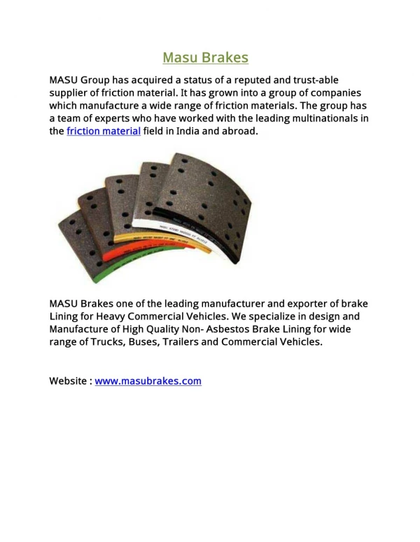
Friction Material Classifications • Organic (non-metallic) • Semi-metallic • Fully metallic • Synthetic
Hydraulic Brake Systems • Uses brake fluid to transfer hydraulic pressure from the master cylinder to the wheel brake mechanisms . • Fluids are not compressible. • In a closed system the pressure is equal to every part in the system at the brake lines regardless of the length line. • Output force can be increased by using a larger piston. • The condition of the piston seals in the master cylinder will influence the amount of pressure developed.
Dual Braking Systems • 1967 federal law requires all vehicles be equipped with two separate brake systems. If one system fails the other provides enough braking power to stop the vehicle. • This is done by using a tandem master cylinder in a dual braking system.
Dual Braking Systems Two Types of Systems Used • Front/Rear Split System Older dual brake systems • Diagonally Split System Newer dual brake systems
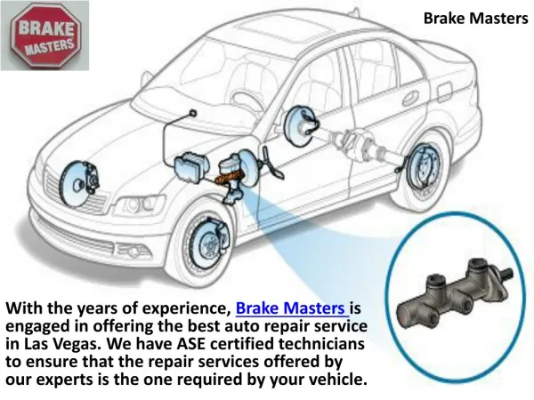
Brake System Components • Brake fluid • Master cylinder • Power booster • Control valves • Wheel brake assemblies • Parking brake • ABS system
Brake Fluid Three Basic Types Dot 3 – most common Dot 4 – has a higher boiling point Both are polyglycol based Both are hydroscopic – (absorb water) Dot 5 – has a higher boiling point than dot 3 or 4 Dot 5 is silicone-based Brake fade can occur when brake fluid boils Most manufacturers recommend changing the fluid periodically. Do not use any other fluid in the brake system.
Master Cylinder Converts mechanical force to hydraulic pressure needed to apply the brake mechanisms. Generates the hydraulic pressure needed to apply the brake mechanisms A) Integral type B) Composite Type Always keep the caps tightly sealed to keep moisture and dirt from contaminating the fluid.
Master Cylinder • Some master cylinders use residual check valves. Used only with drum brakes. • General Motors uses a quick-take-up master cylinder on disc brakes with low drag caliper pistons. • Some master cylinders have a fluid level warning switch. When the fluid level gets low a warning light in the dash comes on.
How the Master Cylinder Works • The master cylinder pushrod is connected to a piston. • Hydraulic fluid is in front of the piston. • When the pedal is pressed, the piston is pushed forward. • The fluid transmits force throughout the system.
Brake Lines and Hoses • Their purpose is to carry brake fluid from the master cylinder to the calipers and wheel cylinders. • Brake lines are made of steel. The ends are made with a special double flare to prevent leaks. • Two types of flare are used – inverted flare and the ISO flare. • Brake hoses offer flexible connections to allow for wheel movement.
Brake System Valves • Metering valve Delays application of front disc brakes until pressure builds to rear drum brakes. • Proportioning valve Applies more hydraulic pressure to the disc brakes to balance braking.
Brake System Valves • Pressure Differential Switch Used to operate a warning switch to alert the driver if pressure is lost in the system. If pressure is lost the switch activates the warning light in the dash. • Combination valve Combines several functions in one valve. Metering, proportioning, and pressure differential valve in one unit.
Brake System Valves • Height-Sensing Proportional Valve When the vehicle is not loaded hydraulic pressure is reduced, and when the vehicle is carrying a load the actuator changes the valve setting to allow full hydraulic pressure. • Stop Light Switch Activates the brake lights when the pedal pressed. May also deactivate the cruise control. • Residual Check Valve Used only with drum brakes, keeps slight pressure in the lines to keep air from getting past the wheel cylinder seals.
Hydraulic System Bleeding • The purpose of bleeding a hydraulic brake system is to : 1) to force trapped air out of the brake fluid 2) replace the old brake fluid 3) remove dust particles and moisture
Hydraulic System Bleeding 3 Types of Bleeding Procedures • Manual Bleeding – requires 2 people, one to pump the brake pedal, and the other to open the bleeder screw. • Pressure Bleeding – using pressure bleeding equipment that forces fluid through the system to remove the air. • Vacuum Bleeding – Uses a vacuum pump to draw fluid out of system Some antilock brake systems require the useof ascan tool to help bleed the brakes.