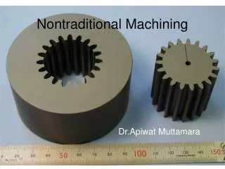
Nontraditional Machining Processes
Learn about the history of material development that led to the creation of nontraditional machining processes. Explore the differences between conventional and nonconventional machining methods, classifications of processes, and advantages and disadvantages of techniques such as Abrasive Jet Machining (AJM).

Nontraditional Machining Processes
E N D
Presentation Transcript
Nontraditional Machining Processes Mr. D. N. Patel
The requirements that lead to the development of nontraditional machining • Very high hardness and strength of the material. (above 400 HB.) • The work piece is too flexible or slender to support the cutting or grinding forces. • The shape of the part is complex, such as internal and external profiles, or small diameter holes. • Surface finish or tolerance better than those obtainable conventional process. • Temperature rise or residual stress in the work piece are undesirable.
Conventional Machining VS NonConventional Machining • The cutting tool and workpiece are always in physical contact, with a relative motion against each other, which results in friction and a significant tool wear. • In non-traditional processes, there is no physical contact between the tool and workpiece. Although in some non-traditional processes tool wear exists, it rarely is a significant problem. • Material removal rate of the traditional processes is limited by the mechanical properties of the work material. Non-traditional processes easily deal with such difficult-to-cut materials like ceramics and ceramic based tool materials, fiber reinforced materials, carbides, titanium-based alloys.
Continue… • In traditional processes, the relative motion between the tool and work piece is typically rotary or reciprocating. Thus, the shape of the work surfaces is limited to circular or flat shapes. In spite of widely used CNC systems, machining of three-dimensional surfaces is still a difficult task. Most non-traditional processes were develop just to solve this problem. • Machining of small cavities, slits, blind or through holes is difficult with traditional processes, whereas it is a simple work for some non-traditional processes. • Traditional processes are well established, use relatively simple and inexpensive machinery and readily available cutting tools. Non-traditional processes require expensive equipment and tooling as well as skilled labor, which increases significantly the production cost.
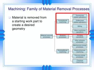
Classification OF Processes • Mechanical Metal removal Processes • It is characterized by the fact that the material removal is due to the application of mechanical energy in the form of high frequency vibrations or kinetic energy of an abrasive jet. • 1. Ultra sonic Machining (USM). 2. Abrasive Jet Machining (AJM). 3. Water Jet Machining (WJM).
Continue… • Electro-Chemical • It is based on electro-chemical dissolution of materials by an electrolyte under the influence of an externally applied electrical potential. 1. Electro-Chemical Machining (ECM). 2. ECG 3 ECD
Continue… • Thermal Method The material is removed due to controlled, localized heating of the work piece. It result into material removal by melting and evaporation. The source of heat generation in such cases can be widely different. 1.Electric Discharge Machining (EDM). 2. Plasma Arc Machining (PAM). 3. EBM 4. LBM
Abrasive Water-Jet Cutting • A stream of fine grain abrasives mixed with air or suitable carrier gas, at high pressure, is directed by means of a nozzle on the work surface to be machined. • The material removal is due to erosive action of a high pressure jet. • AJM differ from the conventional sand blasting process in the way that the abrasive is much finer and effective control over the process parameters and cutting. Used mainly to cut hard and brittle materials, which are thin and sensitive to heat.
Typical AJM Parameters • Abrasive • Aluminum oxide for Al and Brass. • SiC for Stainless steel and Ceramic\ • Bicarbonate of soda for Teflon • Glass bed for polishing. • Size • 10-15 Micron • Quantity • 5-15 liter/min for fine work • 10-30 liter/min for usual cuts. • 50-100 liter/min for rough cuts.
Typical AJM Parameters • Medium • Dry air, CO2, N2 • Quantity: 30 liter/min • Velocity: 150-300 m/min • Pressure: 200-1300 KPa • Nozzle • Material: Tungsten carbide or saffire • Stand of distance: 2.54-75 mm • Diameter: 0.13-1.2 mm • Operating Angle: 60° to vertical
Typical AJM Parameters • Factors affecting MRR: • Types of abrasive and abrasive grain size • Flow rate • Stand off distance • Nozzle Pressure
Advantages of AJM • Low capital cost. • Less vibration. • Good for difficult to reach area. • No heat is genera6ted in work piece. • Ability to cut intricate holes of any hardness and brittleness in the material. • Ability to cut fragile, brittle hard and heat sensitive material without damage • Disadvantages of AJM: • Low metal removal rate. • Due to stay cutting accuracy is affected. • Parivles is imbedding in work piece. • Abrasive powder cannot be reused.
Applications of AJM: • For abrading and frosting glass, it is more economical than acid etching and grinding. • For doing hard suffuses safe removal of smears and ceramics oxides on metals. • Resistive coating etc from ports to delicate to withstand normal scrapping. • Delicate cleaning such as removal of smudges from antique documents. • Machining semiconductors such as germanium etc.
Water Jet Machining • The water jet machining involves directing a high pressure (150-1000 MPa) high velocity (540-1400 m/s) water jet(faster than the speed of sound) to the surface to be machined. The fluid flow rate is typically from 0.5 to 2.5 l/min • The kinetic energy of water jet after striking the work surface is reduced to zero. • The bulk of kinetic energy of jet is converted into pressure energy. • If the local pressure caused by the water jet exceeds the strength of the surface being machined, the material from the surface gets eroded and a cavity is thus formed. • The water jet energy in this process is concentrated over a very small area, giving rise to high energy density(1010 w/mm2) High
Continue… • Water is the most common fluid used, but additives such as alcohols, oil products and glycerol are added when they can be dissolved in water to improve the fluid characteristics. • Typical work materials involve soft metals, paper, cloth, wood, leather, rubber, plastics, and frozen food. • If the work material is brittle it will fracture, if it is ductile, it will cut well: • The orifice is often made of sapphire and its diameter rangesfrom 1.2 mm to 0.5 mm:
Water Jet Equipments • It is consists of three main units (i) A pump along with intensifier. (ii)Cutting head comprising of nozzle and work table movement. (iii) filter unit for debries,pout impurities. • Advantages - no heat produced - cut can be started anywhere without the need for predrilled holes - burr produced is minimum - environmentally safe and friendly manufacturing. Application – used for cutting composites, plastics, fabrics, rubber, wood products etc. Also used in food processing industry.
Abrasive Water jet machining • The rate of cutting in water jet machining, particularly while cutting ductile material, is quite low. Cutting rate can be achieved by mixing abrasive powder in the water to be used for machining. • In Abrasive Water Jet Cutting, a narrow, focused, water jet is mixed with abrasive particles. • This jet is sprayed with very high pressures resulting in high velocities that cut through all materials. • The presence of abrasive particles in the water jet reduces cutting forces and enables cutting of thick and hard materials (steel plates over 80-mm thick can be cut). • The velocity of the stream is up to 90 m/s, about 2.5 times the speed of sound.
Continue.. • Abrasive Water Jet Cutting process was developed in 1960s to cut materials that cannot stand high temperatures for stress distortion or metallurgical reasons such as wood and composites, and traditionally difficult-to-cut materials, e.g. ceramics, glass, stones, titanium alloys
Ultrasonic machining • History • The roots of ultrasonic technology can be traced back to research on the piezoelectric effect conducted by Pierre Curie around 1880. • He found that asymmetrical crystals such as quartz and Rochelle salt (potassium sodium titrate) generate an electric charge when mechanical pressure is applied. • Conversely, mechanical vibrations are obtained by applying electrical oscillations to the same crystals. • Frequency values of up to 1Ghz (1 billion cycles per second) have been used in the ultrasonic industry. • Today's Ultrasonic applications include medical imaging (scanning the unborn fetus) and testing for cracks in airplane construction.
Ultrasonic Waves • The Ultrasonic waves are sound waves of frequency higher than 20,000 Hz. • Ultrasonic waves can be generated using mechanical, electromagnetic and thermal energy sources. • They can be produced in gasses (including air), liquids and solids. • Magnetostrictive transducers use the inverse magnetostrictive effect to convert magnetic energy into ultrasonic energy • This is accomplished by applying a strong alternating magnetic field to certain metals, alloys and ferrites
Continue.. • Piezoelectric transducers employ the inverse piezoelectric effect using natural or synthetic single crystals (such as quartz) or ceramics (such as barium titanate) which have strong piezoelectric behavior. • Ceramics have the advantage over crystals in that they are easier to shape by casting, pressing and extruding.
1- This is the standard mechanism used in most of the universal Ultrasonic machines
Principle of machining • In the process of Ultrasonic Machining, material is removed by micro-chipping or erosion with abrasive particles. • In USM process, the tool, made of softer material than that of the workpiece, is oscillated by the Booster and Sonotrode at a frequency of about 20 kHz with an amplitude of about 25.4 um (0.001 in). • The tool forces the abrasive grits, in the gap between the tool and the workpiece, to impact normally and successively on the work surface, thereby machining the work surface. • During one strike, the tool moves down from its most upper remote position with a starting speed at zero, then it speeds up to finally reach the maximum speed at the mean position.
Continue.. • Then the tool slows down its speed and eventually reaches zero again at the lowest position. • When the grit size is close to the mean position, the tool hits the grit with its full speed • The smaller the grit size, the lesser the momentum it receives from the tool. • Therefore, there is an effective speed zone for the tool and, correspondingly there is an effective size range for the grits. • In the machining process, the tool, at some point, impacts on the largest grits, which are forced into the tool and work piece.
Continue.. • As the tool continues to move downwards, the force acting on these grits increases rapidly, therefore some of the grits may be fractured. • As the tool moves further down, more grits with smaller sizes come in contact with the tool, the force acting on each grit becomes less. • Eventually, the tool comes to the end of its strike, the number of grits under impact force from both the tool and the workpiece becomes maximum. • Grits with size larger than the minimum gap will penetrate into the tool and work surface to different extents according to their diameters and the hardness of both surfaces
Electrochemical Machining • A popular application of electrolysis is the electroplating process in which metal coatings are deposited upon the surface of a catholically polarized metal. • ECM is similar to electro polishing in that it also is an anodic dissolution process. But the rates of metal removal offered by the polishing process are considerably less than those needed in metal machining practice .
Concept • Metal removal is achieved by electrochemical dissolution of an anodically polarized workpiece which is one part of an electrolytic cell in ECM. • when an electric current is passed between two conductors dipped into a liquid solution named as Electrolysis . • Electrolytes are different from metallic conductors of electricity in that the current is carried not by electrons but by atoms, or group of atoms, which have either lost or gained electrons, thus acquiring either positive or negative charges. Such atoms are called ions.
Continue.. • Ions which carry positive charges move through the electrolyte in the direction of the positive current, that is, toward the cathode, and are called cat anions. • The negatively charged ions travel toward the anode and are called anions. • The movement of the ions is accompanied by the flow of electrons, in the opposite sense to the positive current in the electrolyte. • Both reactions are a consequence of the applied potential difference, that is, voltage, from the electric source.
Continue.. • the workpiece and tool are the anode and cathode, respectively, of an electrolytic cell, and a constant potential difference, usually at about 10 V, is applied across them. • A suitable electrolyte, for example, aqueous sodium chloride (table salt) solution, is chosen so that the cathode shape remains unchanged during electrolysis. • The electrolyte is also pumped at a rate 3 to 30 meter/second, through the gap between the electrodes to remove the products of machining and to diminish unwanted effects, such as those that arise with cathodic gas generation and electrical heating. • The rate at which metal is then removed from the anode is approximately in inverse proportion to the distance between the electrodes
Continue.. • As machining proceeds, and with the simultaneous movement of the cathode at a typical rate, for example, 0.02 millimeter/second toward the anode. • the gap width along the electrode length will gradually tend to a steady-state value. Under these conditions, a shape, roughly complementary to that of the cathode, will be reproduced on the anode.
ECM Components (Power) • The power needed to operate the ECM is obviously electrical. There are many specifications to this power. • The current density must be high. • The gap between the tool and the work piece must be low for higher accuracy, thus the voltage must be low to avoid a short circuit. • The control system uses some of this electrical power.
ECM Components (electrolyte circulation system) • The electrolyte must be injected in the gap at high speed (between 1500 to 3000 m/min). • The inlet pressure must be between 0.15-3 MPa. • The electrolyte system must include a fairly strong pump. • System also includes a filter, sludge removal system, and treatment units. • The electrolyte is stored in a tank.
ECM Components (control system) • Control parameters include: • Voltage • Inlet and outlet pressure of electrolyte • Temperature of electrolyte. • The current is dependant on the above parameters and the feed rate.
Advantages • There is no cutting forces therefore clamping is not required except for controlled motion of the work piece. • There is no heat affected zone. • Very accurate. • Relatively fast • Can machine harder metals than the tool • Faster than EDM • No tool wear at all. • No heat affected zone. • Better finish and accuracy.
Disadvantages • More expensive than conventional machining. • Need more area for installation. • Electrolytes may destroy the equipment. • Not environmentally friendly (sludge and other waste) • High energy consumption. • Material has to be electrically conductive.
Applications • The most common application of ECM is high accuracy duplication. Because there is no tool wear, it can be used repeatedly with a high degree of accuracy. • It is also used to make cavities and holes in various products. • Sinking operations (RAM ECM) are also used as an alternative to RAM EDM. • It is commonly used on thin walled, easily deformable and brittle material because they would probably develop cracks with conventional machining.
Products • The two most common products of ECM are turbine/compressor blades and rifle barrels. • Each of those parts require machining of extremely hard metals with certain mechanical specifications that would be really difficult to perform on conventional machines. • Some of these mechanical characteristics achieved by ECM are: • Stress free grooves. • Any groove geometry. • Any conductive metal can be machined. • Repeatable accuracy of 0.0005”. • High surface finish. • Fast cycle time.
Economics • The process is economical when a large number of complex identical products need to be made (at least 50 units). • Several tools could be connected to a cassette to make many cavities simultaneously. (i.e. cylinder cavities in engines). • Large cavities are more economical on ECM and can be processed in 1/10 the time of EDM.