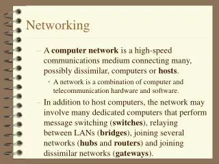
Networking
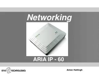
Networking. ARIA IP - 60. Anton Hattingh . Content. Overview Networking Configuration VoIP Connection Admin Programming IP Phone Registration. Overview. ARIA IP - 60 Voice networking provides a way of communication to inter-work with networked system over Internet (VoIP).

Networking
E N D
Presentation Transcript
Networking ARIA IP - 60 Anton Hattingh
Content • Overview • Networking Configuration • VoIP Connection • Admin Programming • IP Phone Registration
Overview • ARIA IP - 60 Voice networking provides a way of communication to inter-work with networked system over Internet (VoIP). • ARIA IP provides uniform numbering plan for all users in the network • The networked systems can be considered as one system. • Extension in any system can talk with other system like extension call • Up to 72 systems can be inter-working via public or private network • ARIA IP supports the total solution from Home office to Headquarter office with ARIA IP - 60 Systems
VOIP Connection 1/2 PSTN VoIP Connection between Systems Master Slave LCO “9” : CO Access Code STA NO 100 ~ 147 STA NO 200 ~ 247 LANU LANU VOIB VOIB LAN Master System Slave System 1. Station range : 100~147 2. MPB IP Address : 165.165.165.60 3. VOIB IP Address : 165.165.165.70 4. CO Line type : (LCOB : Normal, VOIB : ISDN DID) PGM140 5. DID Conversion Type : Type 1 6. CO Range : (LCOB : 1~6, VOIB : 7~14) 7. Net CO Group : (VOIB : Net CO Group 01) (LCOB : Net CO Group 02) 1. Station range : 200~247 2. MPB IP Address : 165.165.165.80 3. VOIB IP Address : 165.165.165.90 4. CO Line type : (VOIB : ISDN DID) PGM140 5. DID Conversion Type : Type 1 6. CO Range : (VOIB : 1~6) 7. Net CO Group : (VOIB : Net CO Group 01)
VOIP Connection 2/2 Master System Slave System 8. Networking Table PGM320 BTN 1 : Net Enable PGM322 (Net CO) BTN 1 : Net CO Group = 01 BTN 4 : Net CO Type = NET or PSTN - VOIB : Net CO Group 01/NET - LCOB : Net CO Group 02/PSTN PGM324 BIN 00 (Master, itself) BTN 1 (Usage) = NET BTN 2 (STA Number) = 1#** BTN 3 (Net CO Gr) = 00 BIN 01 (Slave system) BTN 1 (Usage) = NET BTN 2 (STA Number) = 2** BTN 3 (Net CO Gr) = 01 BTN 4 (CPN) /BTN(1) CPN IP Info 1= 165.165.165.90 BIN 02 (Master system) (*Note 2) BTN 1 (Usage) = PSTN BTN 2 (STA Number) = 9 (*Note 1) BTN 3 (Net CO Gr) = 02 8. Networking Table PGM320 BTN 1 : Net Enable PGM322 (Net CO) BTN 1 : Net CO Group = 01 BTN 4 : Net CO Type = NET or PSTN - VOIB : Net CO Group 01/NET PGM324 BIN 00 (Slave, itself) BTN 1 (Usage) = NET BTN 2 (STA Number) = 2#** BTN 3 (Net CO Gr) = 00 BIN 01 (Master system) BTN 1 (Usage) = NET BTN 2 (STA Number) = 1** BTN 3 (Net CO Gr) = 01 BTN 4 (CPN) /BTN(1) CPN IP Info 1 = 165.165.165.70 BIN 02 (Master system) (*Note 2) BTN 1 (Usage) = PSTN BTN 2 (STA Number) = 9 (*Note 1) BTN 3 (Net CO Gr) = 01 BTN 4 (CPN) /BTN(1) CPN IP Info 1 = 165.165.165.70 BTN 7 (Digit Repeat) = Yes * Note 1 : Delete 1st CO Group Access Code (PGM107) in advance. * Note 2 : A station in slave system can access the LCOB lines of master system by dialing “9”. “9” should not be used in numbering plan.
Admin Programming This section provides a step-by-step procedure on how to set-up the network parameters on the iPLDK 60 systems to network iPLDK 60 systems together. • System configuration • Ensure that the VOIM module is connected and recognised by the system, PGM101. • The VOIM expansion module will occupy slot 10.
Station numbering plan SYSTEM 2 SYSTEM 1 When networking systems together the station-numbering plan of the systems will be different. This is configured in PGM104.
CO line Attributes The VOIB CO lines must be configured as ISDN DID/MSN (PGM 140) and the ISDN Line Attributes (PGM 143: DDI Conversion and Remove Digits) must be configured as required by network numbering scheme. The CO Lines to be configured can be determined by right clicking on VOIB slot in PGM101, select “CO Data View”.
CO line Attributes The CO Line Attribute Window, PGM140, will be opened and the VOIB CO lines will be listed. These CO Lines should be configured as ISDN DID.
CO line Attributes The CO Line ISDN Attributes (PGM143), “DID Conv type” 1 and “DID Remove Num” 0 must be set as required by the Network Numbering plan
Network Basic Attributes To enable the networking function PGM320 Flex1, Networking Enable must be set to ON for all the systems, which are required to inter-work over the network.
Network CO line Attributes In this section the Network CO lines groups are defined. The Network CO lines must be allocated to a particular Net CO group. The network CO Line type must also be defined as NET.
Network Numbering plan table The final step is to set up the Network Numbering plan PGM 324 the numbering plans of the various systems are defined. • Bin 00 will define the numbering plan of the local system and this Bin must utilise Net Number CO Group 0. • Bin 01-71 will define the numbering plan of the remote systems and these bins will utilise the required Net Number CO Group defined for NET CO in PGM 322.
VOIP Attributes VOIB requires the VOIB card to be allocated an IP address as well as to define the gateway address. These VOIB Attributes are configured in PGM340.
Logical Slot Assignment When VOIM module is utilised, the virtual slot number (99) should be entered to STA or COL logical slot. The system should now be RESET for this programming to take effect. N.B.!
IP Phone Registration The VOIB slot for RSG/IP phone and VOIB channel to be used for IP Phone is defined in PGM380.
IP Phone Registration To register IP Phones (LIP7000) to the system the MAC address of the IP phone should be entered in PGM386. The MAC address is found on a sticker on the back of the IP Phone. The IPECS Softphone/Phontage is registered to the system as an IP Phone. The MAC address of the PC LAN card must be entered in PGM 386.
IP Phone Settings The IP Phone needs to be configured to register to the ARIA IP - 60. On the IP Phone it is necessary to select the connection Mode as Remote, enter IP Phone IP address, enter VOIM IP address and Gateway Address. When power up the IP Phone, the following message is displayed on LCD. 1. To retry registration to system, press [#]. 2. To change the value related with registration, press [*]
IP Phone Settings You can move the menu by pressing [Volume Up] or [Volume Down] after each setting press Hold/Save to Save changes. 3. Change the mode (LOCAL/REMOTE). FOR OptiCon IP must set ‘REMOTE MODE’. 4. Change the DHCP setting (DISABLED/ENABLED). Disable DHCP Mode 5. Change the Device number (Not Used)
IP Phone Settings 6. Enter or change VOIB IP Address. On ARIA IP - 60 this will be the IP address of VOIM Module. 7. Enter or change Router IP Address. 8. Enter or change Net Mask. 9. Enter or change Phone IP Address 10. Once all the necessary parameters have been changed press the Speaker button to search for system.