Comprehensive Guide to Cabling and Infrastructure for Enterprise Wireless Networks
This training program on cabling and infrastructure for wireless networks covers essential topics such as wireless LAN design, cellular systems, and specialized applications in healthcare settings. Led by Scott D. Thompson from Oberon, Inc., it focuses on effective installation and mounting techniques for access points, as well as compliance with IEEE standards. Participants will gain insights into designing robust wireless networking solutions, while earning BICSI Continuing Education Credits. It’s vital for professionals involved in network infrastructure and wireless technology.

Comprehensive Guide to Cabling and Infrastructure for Enterprise Wireless Networks
E N D
Presentation Transcript
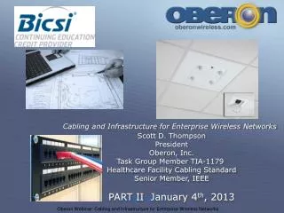
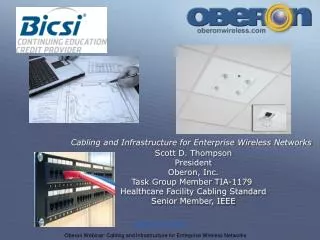
Cabling and Infrastructure for Enterprise Wireless Networks Scott D. Thompson President Oberon, Inc. Task Group Member TIA-1179 Healthcare Facility Cabling Standard Senior Member, IEEE Link-Up 10-13-2010
Effective November 1, 2010, BICSI recognizes Cabling and Infrastructure for Wireless Networks Part I training for the following BICSI Continuing Education Credits (CECs). “Note: Recognition of BICSI CECs does not mean that BICSI endorses, accredits, approves, or sanctions a course in any way. CECs are assigned based upon represented course content only and are not the result of an in-depth evaluation of instructional quality” Link-Up 10-13-2010
Oberon manufactures ceiling and wall mounted Tele- communications Enclosures (TEs) for wireless LAN access points, DAS equipment, multimedia gateways and other networking components Wireless AP enclosure Workspace Telecom Enclosures Link-Up 10-13-2010
AGENDA PART 1 December 5 2012 • Wireless LAN (Wi-Fi) and Cellular (DAS) • Wireless networking design basics • Cabling for wireless networks • Installing and mounting the access points • PART 2 January 16 2013 • Wireless in Healthcare & Hospitals • Cabling for IEEE 802.11n and 802.11ac wireless access points • Emerging applications- wireless projectors, Multimedia gateways, etc. Link-Up 10-13-2010
Growth in Global Mobile Data IEEE 802.3 Ethernet Bandwidth Assessment Ad Hoc and Cisco 2010 visual networking index Link-Up 10-13-2010
Wireless LAN (WiFi), Cellular (DAS), and Public Safety Wireless LAN (Wi-Fi™) • Uses unlicensed spectrum at 2.4 and 5 GHz • Network interface is standards based IEEE 802.3 Ethernet on category twisted pair cabling • Usually engages “Wi-Fi™ Certified” products • Generally paid for and operated by the network owner Link-Up 10-13-2010
Wireless LAN (WiFi), Cellular (DAS), and Public Safety Distributed Antenna System (DAS) and Public Safety • Uses licensed spectrum at 400 (PS), 700 (4G), 800, 850, 900, 1800, 1900, 2100 MHz. Owned by mobile service provider • Network interface may be proprietary waveform over twisted pair, optical, or coaxial medium • Paid for by the network owner, mobile service provider, property owner, third party neutral host or combination Link-Up 10-13-2010
Wireless LAN (Wi-Fi), Cellular (DAS), and Public Safety Infrastructure differences between Wi-Fi and Cellular • Cabling, coverage, capacity, reliability, and backup requirements will be different • Propagation and antenna placement is different • Although the infrastructure may be different, cost savings may be realized by simultaneous design and installation Link-Up 10-13-2010
Wireless LAN (WiFi), Cellular (DAS), and Public Safety Trends • Cellular spectrum is very limited! • Spectrum re-use will help stretch capabilities • In-building DAS and micro-cellular systems reduce loading on the outdoor macro-cellular mobile network • Off-load traffic from cellular network to wireless LAN • The solution is a combination of micro-cellular networks and off-loading to Wi-Fi- both require in-building cabling Link-Up 10-13-2010
Wireless Networking Design Basics • Requirements gathering • Define the client devices to be used • Define the applications to be used • Define the coverage area and density of users • Document initial assumptions, AP configs, antennas used in survey, cable lengths, etc. Link-Up 10-13-2010
Wireless Networking Design Basics • Perform a site survey • Set the access point transmit power level to the same level as your critical client devices • http://transition.fcc.gov/oet/ea/fccid/ • Identify the fringe based on minimum Received Signal Strength Indication (RSSI) or Signal to Noise ratio (SNR). Typically in the -75 to -60 dBm range • Remember that different client devices may receive different signal levels based on client antenna styles Link-Up 10-13-2010
Wireless Networking Design Basics Link-Up 10-13-2010
Wireless Networking Design Basics • Engage 802.11n access points – cabled infrastructure should support 1 gigabit interfaces • Prepare for 802.11ac • Engage WMM (wireless multimedia) for QoS • Exploit the 5 GHz band (21 non-overlapping channels, versus 3 non-overlapping channels at 2.4 GHz) • Implementation should closely match the survey Link-Up 10-13-2010
Wireless Networking Design Basics 3 channel Plan at 2.4 GHz 11 1 6 1 11 6 1 1 11 6 Link-Up 10-13-2010
Wireless Networking Design Basics 3 channel Plan at 2.4 GHz Plus, 21 channel 5GHz overlay 120 108 116 136 52 104 36 132 112 56 44 140 40 128 48 60 124 64 100 Link-Up 10-13-2010
CABLING FOR WIRELESS Link-Up 10-13-2010
TSB-162 –Guidelines for Wireless Telecommunications Systems Bulletin TSB-162 Telecommunications Cabling Guidelines for Wireless Access Points (APs) Provides guidelines on the topology, design, installation, and testing of cabling infrastructure for supporting wireless local area networks (WLANs) Link-Up 10-13-2010
TSB-162 Guidelines for Wireless TSB-162 states that cabling (for wireless access points) should be installed and performance tested per existing 568-B.2 standards. (Now 568-C.2) Determination of exact cell size and placement of the wireless access point (WAP) is outside the scope of the TSB (recommends perform a site survey or simulation) Link-Up 10-13-2010
TSB-162 Pre-Cabling Guidelines for Wireless Access Points 5,540 sq.ft. circular cell AP Lmax=13 m (42 ft) Hmax=81 m (265 ft) TR TO TO r=13m (42 ft) Patch=6m (20 ft) EQUIPMENT (switch) Equipment in the Telecom Room TO X=18.3 m (60 ft) TO TO 3,600 sq.ft. square cell Meeting room Link-Up 10-13-2010
TSB-162 Pre-Cabling Guidelines for Wireless Access Points Link-Up 10-13-2010
TSB-162 Cabling Guidelines • for Wireless Access Points • Accepts an in-the-grid ceiling mount, with antenna un-obstructed by ceiling tiles • Accepts wall mount above or below suspended ceiling. AC power must be in an approved enclosure above the ceiling • Telecommunications Enclosures (TEs) can be mounted in a ceiling panel to provide locked security or aesthetics for APs • Consider maintenance and security of APs • Observe separation of power and network cabling • Local power or PoE acceptable (end span or mid span) • Horizontal should be terminated at E.O., then patch to AP Link-Up 10-13-2010
INSTALLING ACCESS POINTS Link-Up 10-13-2010
Installing access points and DAS remotes • Method 1: Above the ceiling • Method 2: Attach to ceiling grid • Method 3: In a ceiling enclosure or locking mount • Method 4: On the wall • Outdoors Link-Up 10-13-2010
Preferred installation orientation AP on the ceiling grid AP above drop ceiling AP in enclosure AP on the wall Link-Up 10-13-2010
Method 1: Above the ceiling- things to avoid Cracked ceiling tile A lot of metal “Poke thru” antenna Link-Up 10-13-2010
Method 1: Above the ceiling • Equipment should be UL 2043 “Plenum rated” • Use a hanger sturdy enough for AP, use a support wire Support Wire Oberon P/N 1045-00 above-ceiling hanger Link-Up 10-13-2010
Method 2: On the Ceiling Grid • Avoid lifting ceiling tile • Minimize hole in tile • Conceal cable • Lock AP Link-Up 10-13-2010
Method 3: Install access point in a ceiling Enclosure or locking mount Oberon Model 1052-00 Ceiling enclosure with Antennas mounted on door Link-Up 10-13-2010
Method 3: Install access point in a ceiling enclosure or locking mount Link-Up 10-13-2010 Model 1052-00 Model 1072-00
Method 3: Install access point in a ceiling enclosure or locking mount Model 1057-00 Model 1052-AP135 Model 1052-WA Model 1052-3510 Model 1059-00 Model 1052-CCOAP Link-Up 10-13-2010
Method 4: Install access point on the wall Link-Up 10-13-2010
Method 4: Install access point on the wall Right Angle Bracket Surface mount lock box Recess Wall Mounts Model 1029-00 Model 1030-00 Model 1032-00 Link-Up 10-13-2010
Outdoors: Use a NEMA 4 or NEMA 4X enclosure • Power dissipation of access points is low, so ventilation is not required. • Select an AP with extended temperature range. De-rate AP accordingly when in enclosure • App Note on de-rating AP in enclosure at • http://www.oberonwireless.com/additional-resources.php • Keep enclosure out of direct sunlight • Avoid large metal walls Link-Up 10-13-2010
Outdoors: Use a NEMA 4 or NEMA 4X enclosure Model 1024-00 wall and mast mount Model 1020-PS under seating Link-Up 10-13-2010
Why use a wireless access point enclosure? • Enclosures provide physical security, and protect the AP from tampering, accidental moves, disconnects, damage and obstructions, thereby preserving the integrity of the site survey. • Enclosures serve as a convenient place to terminate and conceal data and antenna cables. Cable certification can be performed by the installer “to the enclosure”, and the access point can be installed thereafter. • Enclosures can improve the aesthetics or appearance of the installation. The ceiling is the ideal location for antennas. • Code or directive compliance. For example in Healthcare environments, ceiling enclosures provide easy access to the AP for moves, adds, & changes without exposing the air handling (plenum) space, simplifying infection control Link-Up 10-13-2010
END OF PART I • PART 2 January 16 2013, 1:00 p.m. • Wireless in Healthcare • Cabling for IEEE 802.11n and 802.11ac wireless access points • Emerging applications- wireless projectors, multimedia gateways, etc. Scott D. Thompson sdt@oberonwireless.com www.oberonwireless.com Link-Up 10-13-2010