Download
1 / 23
230 likes | 477 Vues
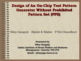
Design of An On-Chip Test Pattern Generator Without Prohibited Pattern Set (PPS). Niloy Ganguly Biplab K Sikdar P Pal Chaudhuri. Presented by Niloy Ganguly Indian Institute of Social Welfare and Business Management. Calcutta 700 073 Email : niloy@ppc.becs.ac.in. The Coverage.

E N D
Design of An On-Chip Test Pattern Generator Without Prohibited Pattern Set (PPS) Niloy Ganguly Biplab K Sikdar P Pal Chaudhuri Presented by Niloy Ganguly Indian Institute of Social Welfare and Business Management. Calcutta 700 073 Email : niloy@ppc.becs.ac.in
The Coverage • Introduction and Overview • Cellular Automata Preliminaries • Proposed Design of TPG • Experimental Results • Concluding Remarks ASP-DAC/VLSI Design 2002
Problem Definitions • Prohibited Pattern Set (PPS) – A set of patterns input of which sents the system into an unstable state. • Example : Toggle State of a flip flop • Design a TPG with the following features • It avoids the generation of such PPS • It maintains the randomness and fault coverage of a Pseudo Random Pattern Generator • Side by side it doesn’t add to any hardware cost ASP-DAC/VLSI Design 2002
Problem Definitions • Non Max Length GF(2) Cellular Automata is employed to obtain the design criteria • Design the CA in such a way so that it has large cycles free from PPS • Design a TPG with the following features • It avoids the generation of such PPS • It maintains the randomness and fault coverage of a Pseudo Random Pattern Generator • Side by side it doesn’t add to any hardware cost ASP-DAC/VLSI Design 2002
Clock CL Flip - Flop Q D From left neighbor From right neighbor Combinational logic Cellular Automata Machine A powerful computing and modeling tool • 50’s - J von Nuemann 80’s - Wolfram • A CA consists of an array of cells • A CA cell is essentially a memory element (D Flip flop) with some combinational logic - an XOR and/or XNOR Gate (additive) ASP-DAC/VLSI Design 2002
Clock CL Flip - Flop Q D From left neighbor From right neighbor Combinational logic Cellular Automata Machine A powerful computing and modeling tool • The cell is updated at every clock cycle • The state of the cell is dictated by the immediate neighbors • Typically termed as Two State Three neighborhood Cellular Automata ASP-DAC/VLSI Design 2002
1 0 0 0 0 0 1 1 0 0 T = 0 1 1 1 0 F = [1 0 1 0 1] 0 0 0 1 1 0 0 0 0 1 GF(2) Cellular Automata • The operation of XOR and XNOR rules can be conceived as mod two multiplication and addition • The operations thus can be mapped to operations of Galois Field(2) giving rise to GF(2) Cellular Automata. • The CA is characterized by a T matrix which is essentially the dependency matrix ASP-DAC/VLSI Design 2002
1 0 0 0 0 0 1 1 0 0 T = 0 1 1 1 0 F = [1 0 1 0 1] 0 0 0 1 1 0 0 0 0 1 GF(2) Cellular Automata • For 3-neighborhood CA, we have a band matrix • An XNOR CA is characterized by a inversion vector F indicating the cells where XNOR operation has been performed ASP-DAC/VLSI Design 2002
5 13 6 2 8 7 12 0 9 15 1 4 3 14 10 11 Non Maximum Length CA 3 6 11 2 5 13 9 0 1 Maximum Length CA 10 12 15 14 4 8 7 State Transition Behavior • Group CA - All states lie on some Cycle Our TPG Design is based on this type of CA ASP-DAC/VLSI Design 2002
8 7 6 5 10 1 12 11 13 14 15 0 3 4 9 2 2 13 3 12 5 10 4 11 7 6 15 14 8 9 0 1 State Transition Behavior • Additive variant of Group CA Equal Length CA Our TPG Design is based on this type of CA Non Group CA : Cyclic/ Non cyclic and Non Reachable States ASP-DAC/VLSI Design 2002
Overview of Design Given PPS 0000110 0000010 0001001 0000111 PPS = 0001111 0010100 1101101 1011001 0100100 0010001 Choose a Non Maxlength CA ASP-DAC/VLSI Design 2002
Redundant Cycle(RC) Overview of Design Criterion for choosing Non-Max Length CA • Large cycle of length close to a Max length Cycle • All members of PPS fall in smaller cycles Choose a Non Maxlength CA Target Cycle(TC) ASP-DAC/VLSI Design 2002
Redundant Cycle(RC) Dmax Overview of Design Criterion for choosing Non-Max Length CA • Large cycle of length close to a Max length Cycle • All members of PPS fall in smaller cycles • In Practical Situation all members of PPS don’t fall in RC. • Then Sacrifice a small part of TC Target Cycle(TC) ASP-DAC/VLSI Design 2002
Design of TPG without PPS • C1: Find n-cell CA having RCs and TC • C2: Let most of the members of PPS fall in RC • C3: Find Dmax in TC to avoid remaining PPS • Acceptable Criteria • TC 2n-1 for n > 16 • TC .75 x 2n for n 16 • Dmax 10% of TC ASP-DAC/VLSI Design 2002
Design Simplification : Form CA with 2 RCs besides the all zero cycle Value of RCs to form big TC CA Size n 7 Divide n = n1 + n2 7 = 4 + 3 n1 and n2 are mutually prime Cycle Length RC1 = 2n1 –1 15 Cycle Length RC2 = 2n2 –1 7 Cycle Length TC = 2n1 –1 x 2n2 –1 105 Method of selecting RC ASP-DAC/VLSI Design 2002
Selection of n1 and n2 • Each RC forms a vector subspace • Evolve strategy to partition PPS in two vector subspace • Randomly partition PPS into two sets S1 and S2 • Calculate rank of S1(r1) and S2(r2) • Select a partition where • r1 + r2 n • r1 and r2 are mutually prime • The acceptable criterion of TC is met • Set n1 = r1 and n2 = r2 • T matrix can be designed with maximum member of PPS falling in smaller cycles ASP-DAC/VLSI Design 2002
Heuristic to Design the TPG Problem Since a CA forms a Band Matrix all linear transform is not supported by CA • Randomly Synthesize a non-maximal length group CA • Method - illustrated in paper • CA Toolkit -http://ppc.becs.ac.in • Maximum member of PPS falls in RCs • Find Dmax of rest of PPS covered by TC • Select CA with acceptable criteria ASP-DAC/VLSI Design 2002
Heuristic to Design the TPG Acceptable Criteria Dmax – 10% of TC • Randomly Synthesize a non-maximal length group CA • Method - illustrated in paper • CA Toolkit -http://ppc.becs.ac.in • Maximum member of PPS falls in RCs • Find Dmax of rest of PPS covered by TC • Select CA with acceptable criteria ASP-DAC/VLSI Design 2002
*Indicates that the cycle length approx. 2n – 2n/2 Experimental Observation-I • Real data of PPS is not available • PPS randomly generated, no. of prohibited patterns assumed 25 • For a particular n, 10 different PPS are considered ASP-DAC/VLSI Design 2002
Experimental Observations -II Study of randomness property Platform used is DiehardC Compared with corresponding maximal length CA ASP-DAC/VLSI Design 2002
Experimental Observations -III Fault coverage of the proposed design(Compared with MaxLength CA) Fault Simulator used : Cadence `verifault’ ASP-DAC/VLSI Design 2002
Conclusion • Based on analytical framework of CA theory, the real life problem of PPS is addressed • Solution does not incur extra overhead • Fault efficiency of the TPG is as good as the existing designs ASP-DAC/VLSI Design 2002
Thank you Niloy Ganguly ASP-DAC/VLSI Design 2002