More Potential Divider Circuits
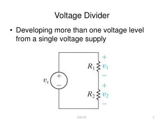
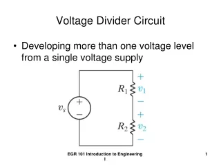
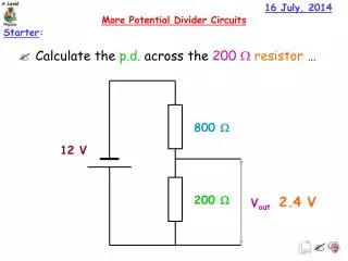
16 July, 2014. More Potential Divider Circuits. Starter :. Calculate the p.d. across the 200 W resistor …. 800 W. 12 V. 200 W. 2.4 V. V out. 16 July, 2014. More Potential Divider Circuits. Learning Outcomes :. At the end of this lesson you should:.

More Potential Divider Circuits
E N D
Presentation Transcript
16 July, 2014 More Potential Divider Circuits Starter: • Calculate the p.d. across the 200 Wresistor … 800 W 12 V 200 W 2.4 V Vout
16 July, 2014 More Potential Divider Circuits Learning Outcomes: At the end of this lesson you should: ALL:Describe how the resistance of a light dependent resistor (LDR) depends on the intensity of light MOST:Explain the use of Thermistor and light dependent resistors in potential divider circuits SOME: Evaluate the advantages of using data-loggers to monitor physical changes
16 July, 2014 More Potential Divider Circuits Keywords: intensity, LDR, light, p.d., resistor, rheostat, potential, switch, temperature, thermistor, transistor, voltage. Tasks: • Make notes on LDRs, thermistors and their uses in potential divider circuits. • Complete the worksheets on More Potential Divider Circuits. Extension: Evaluate the advantages of using data-loggers to monitorphysical changes.
Learning Outcome: Explain the use of thermistors and light dependent resistors in potential divider circuits LDRs and Thermistors: NTCThermistor Light dependent resistor (LDR)
Learning Outcome: Explain the use of thermistors and light dependent resistors in potential divider circuits The Light Dependent Resistor (LDR): The circuit symbol for a light dependent resistor (____) is: LDR The ________ of an LDR depends upon the light intensity. In bright light the LDR has a ___ resistance. In the ____ it has a ____ resistance. resistance low dark high
Learning Outcome: Explain the use of thermistors and light dependent resistors in potential divider circuits The Light Dependent Resistor (LDR): The graph shows how the resistance of a LDRchanges with light intensity …
R Learning Outcome: Explain the use of thermistors and light dependent resistors in potential divider circuits Using a LDR for a Light Sensor: The resistor, R, has a value so that in daylight the p.d. across it is almost equal to the supply voltage. Hence Vout is very small
R Learning Outcome: Explain the use of thermistors and light dependent resistors in potential divider circuits Using a LDR for a Light Sensor: When it becomes dark the resistance of the LDR ________. The p.d. across it also ________. increases increases Hence Voutincreases
R Learning Outcome: Explain the use of thermistors and light dependent resistors in potential divider circuits Using a Transistor: A transistor can be connected to Vout which will switch on a light when the p.d. is bigger than 0.7 V.
R R Learning Outcome: Explain the use of thermistors and light dependent resistors in potential divider circuits Using a LDR for a Light Sensor: If you want the light to switch on during the day time, this can be achieved by swapping the positions of the resistor and the LDR. What is the effect of changing the fixed resistor for a variable resistor?
Learning Outcome: Explain the use of thermistors and light dependent resistors in potential divider circuits The Thermistor (NTC): The circuit symbol for a thermistor is: The resistance of a NTC (_______ __________ _________) thermistor depends upon the temperature. When hot the thermistor has a ___ resistance. When ____ it has a ____ resistance. temperature negative coefficient low cold high
Learning Outcome: Explain the use of thermistors and light dependent resistors in potential divider circuits The Thermistor (NTC): The graph shows how the resistance of a NTC thermistorchanges with temperature …
R Learning Outcome: Explain the use of thermistors and light dependent resistors in potential divider circuits Using a Thermistor for a Temperature Sensor: The resistor, R, has a value so that at room temperature the p.d. across it is almost equal to the supply voltage. Hence Vout is very small
R Learning Outcome: Explain the use of thermistors and light dependent resistors in potential divider circuits Using a Thermistor for a Temperature Sensor: When it becomes colder the resistance of the thermistor ________. The p.d. across it also ________. increases increases Hence Vout increases
R Learning Outcome: Explain the use of thermistors and light dependent resistors in potential divider circuits Using a Thermistor for a Temperature Sensor: How could you make a fire alarm …
16 July, 2014 More Potential Divider Circuits Plenary: Now you should: ALL:Describe how the resistance of a light dependent resistor (LDR) depends on the intensity of light MOST:Explain the use of thermistors and light dependent resistors in potential divider circuits SOME: Evaluate the advantages of using dataloggers to monitor physical changes •
Learning Outcome: Explain the use of thermistors and light dependent resistors in potential divider circuits Homework: Deadline: