Download
1 / 32
320 likes | 442 Vues
The Time Domain Sampler (TDS) utilizes cutting-edge technology based on previous instruments designed for the STEREO mission at the University of Minnesota. It captures impulsive events with precise timing and programmable parameters, maintaining a fixed sampling rate of 1.92 MSa/s. TDS prioritizes quality by adjusting the selection of events based on programmable criteria. Its architecture ensures reliable communication with spacecraft systems, managing telemetry and memory efficiently for optimal data collection. The sampler's key functions support the comprehensive measurement of electric and magnetic fields in various space environments.

E N D
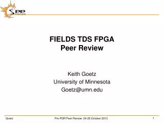
FIELDSTime Domain SamplerPeer Review Keith Goetz University of Minnesota Goetz@umn.edu
Heritage • Time Domain Sampler (TDS) is based on previous instruments • Based most recently on STEREO instrument • Gathers impulsive events • Centered peaks • Simultaneous sampling on all channels • Smooth activity - new • Fixed sampling rate – 1.92MSa/s • Programmable effective sampling rate • Programmable event duration • Events have peaks • After that, flight software rates event based on programmable criteria • Quality can be adjusted – up or down - after the fact • When telemetry is available (nominally to DCB), best event is sent • When memory is needed (for a new event), worst event is deleted • Event selection can be based on quality or not – honesty • Low rate stream gives peak activity as a function of time
Analog Inputs • Channel 1 (ADCs want 0V to 2V at <=1MHz) • V1MF • EPARMF • Channel 2 • V2MF • V3-4MF • Channel 3 • V3MF • V1-2 MF • Channel 4 • V4 MF • B MF • SWEAP counts • ? • Unused • V5MF • V1REF, V2REF, V3REF, V4REF, V5REF • V1-2REF, V3-4REF, EPARDC • V1DUST, V2DUST, V3DUST, V4DUST, V5DUST
FIELDS/TDS Evolution FIELDS was proposed as a single string instrument Within FIELDS, TDS was proposed as a single science board
TDS Evolution In early 2013, Project recognized that FIELDS was central to meeting threshold science – occupying 4 of 9 blocks
TDS Evolution – System-6 • FIELDS then suggested a number of alternatives • increasing reliability • Eventually, we settled on System-6
TDS Requirements • TDS-01Mission Length • TDS Components must be selected to withstand the environment of SPP for the duration of the mission. • TDS-02Spacecraft Interface Compliance (General) • TDS shall implement the spacecraft interface protocol… • TDS-03Timing from S/C • TDS shall provide latching facility upon detection of the "Virtual 1PPS" S/C timing signal… • TDS-04 • Timing from DCBTDS shall provide an electrical interface to the Data Control Board capable of…
SWEAP Requirements • TDS-05 SWEAP Interface - CDI • TDS shall provide an electrical interface to the SWEAP instrument capable of sending CDI commands, receiving CDI messages: • [a] sending Command/Data Interface (CDI) messages to SWEAP; • [b] receiving SWEAP status and burst information from SWEAP; • [c] sending TDS time-keeping information; • [d] sending TDS clock synchronization. • TDS-06 SWEAP Interface – Particles • TDS shall provide an electrical interface to the SWEAP instrument capable of: • [a] receiving particle count information from SWEAP • [b] receiving particle synchronization and state information from SWEAP
MAG Requirements • TDS-07 MAG Interface – CDI • TDS shall provide an electrical interface to the MAG Electronics capable of: • [a] setting control registers • [b] receiving MAG Science and Engineering data • [c] provide MAG AC heater synchronization
AEB Requirements • TDS-08 Antenna Electronics Board Interface (AEB) • TDS shall provide an electrical interface to the Antenna Electronics Board capable of: • [a] setting Biasing D/A converters and relays • [b] reading back the biasing voltages • [c] provide DC-DC converter synchronization
LNPS Requirements • TDS-09Low Noise Power Supply Interface (LNPS) • TDS shall provide an electrical interface to the Low Noise Power Supply capable of • [a] setting control registers for Power Control and Housekeeping Channel • [b] receiving an analog housekeeping signal • [c] provide DC-DC synchronization
TDS Requirements • TDS-10 Time Domain Sampler Control • TDS shall provide electrical interfaces to the Time Domain Sampler data acquisition system capable of: • [a] setting TDS instrument modes • [b] receiving TDS instrument data • TDS-11 TDS Memory Management • TDS shall include memory such that: • [a] is capable of storing ~20 TDS snapshot events • [b] allows best available event to be sent to telemetry • TDS-12 TDS Instrument Calibration • TDS analog science and analog housekeeping conversion coefficients are determined and provided prior to S/C Integration to include gain, phase and timing
Science Requirements • TDS-13 E Signals • TDS shall provide an electrical interface capable of: • [a] signal processing and measurement of the low frequency component of E-Field signals • TDS-14 E Signals • TDS shall provide an electrical interface capable of: • [a] signal processing and measurement of the AC or plasma frequency (ranging to ~1MHz) component of E-Field signals." • TDS-15 B Signals • TDS shall provide an electrical interface capable of: • [a] signal processing and measurement of the AC or plasma frequency (ranging to ~1MHz) component of B-Field signals (single axis)." • TDS-16 Instrument Calibration • TDS shall provide calibration parameters and algorithms so as to allow conversion from telemetry units to physical units (gain and offset per channel) prior to S/C Integration.
TDS – Single Board Data Acquisition System • Centers on RTAX4000 FPGA daughter board • Holds all logic, interfaces and LEON 3 processor instantiation • TDS event data gathered by 16-bit ADCs at ~2MSa/s • Multiplexed 16-bit data bus • Simultaneous acquisition of SWEAP particle counts • TDS event data stored directly into dedicated event memory • 16MB event SRAM – 8 parts – 512k by 32bits • Circular buffers • Processor support • 8-bit data bus • Local SRAM w/ ECC • Local boot PROM (some in FPGA?) • Local program EEPROM • S/C serial interfaces • CDI interfaces to DCB, MAG, SWEAP • Device interfaces – AEB, LNPS • Mezzanine interface • Diagnostic UARTs
Issues • Design is advanced • Based on earlier implementation • More than usual at this point (PDR) • Selected ADC is great – but plastic • A cousin was used on STEREO • Putative parts have been obtained (x100) • Lead has been added • DPA has been completed (x5) well • Radiation and Beam • Up-screening • Backup solutions could be painful in performance and power • Overall power • We’re only now getting to good power estimates • Descope alternatives exist • LVDS protection solution is still open
Next • Continue development work with BB2 • FPGA • FSW • Spacecraft Emulator • FIGs for DCB, MAG and SWEAP • Ground software • Modify existing schematic for ETU • Layout ETU
Waveform Zoomed CLK ~2MHz Samples Δt = 500ns V(t) Δt = 500ns count(t)
Waveform Zoomed! Samples Δt = 500ns t = 1,500ns t = 2,000ns t = 2,500ns t = 3,000ns t = 3,500ns t = 4,000ns t = 4,500ns t = 5,000ns V(t) Δt = 500ns V = 0mV V = -2mV V = -4mV V = +5mV V = -12mV V = -15mV V = -10mV V = -5mV count(t) n = 2 n = 4 n = 2 n = 2 n = 7 n = 3 n = 5
Sweep sync Samples Δt = 500ns t = 1,500ns t = 2,000ns t = 2,500ns t = 3,000ns t = 3,500ns t = 4,000ns t = 4,500ns t = 5,000ns V(t) Δt = 500ns V = 0mV V = -2mV V = -4mV V = +5mV V = -12mV V = -15mV V = -10mV V = -5mV count(t) n = 2 n = 4 n = 2 n = 2 n = 7 n = 3 n = 5 sync(t) t = 2,500ns