Download
1 / 21
210 likes | 412 Vues
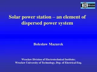
Solar power station – an element of dispersed power system. Wroclaw Division of Electrotechnical Institute; Wroclaw University of Technology, Dep. of Electrical Eng. Bolesław Mazurek. Solar power system. T-s Diagram of Rankine cycle. Theoretical and real characteristics of fuel cell.

E N D
Solar power station – an element of dispersed power system Wroclaw Division of Electrotechnical Institute; Wroclaw University of Technology, Dep. of Electrical Eng. Bolesław Mazurek
Vehicle mechanism hydrogen H2O oxygen in the middle ion H3O oxygen H3O
PEM Fuel Cellreactions: Anode reaction: 2H2 4H+ + 4e- Cathode reaction: O2 + 4H+ + 4e- 2H2O Summary raction: 2H2 + O2 2H2O
hydrogen oxygen FUEL SOFC AIR electrolyte Pt cathode Pt anode SOFC Fuel Cellreactions: Cathode reaction: 1/2O2 + 2e- O2- Anode reactions: H2 + O2- H2O + 2e- CO + O2- CO2 + 2e- CH4+4O2- 2H2O + CO2 + 8e- Summary reactions: H2 + 1/2O2 H2O
New electrolytes elaborated in IEL/OW for SOFC application Also investigation of scandium stabilized zirconium oxide (e.g. ScSZ)
Fig.1 Diagram of the system for measurement of the ionic conductivity,DC four probe Wagner method. Fig.2 Diagram of the test stand for measurement of the ionic conductivity, IS impedance spectroscopymethod. Ionic conductivity measurements
- in reducing atmosphere - in oxide Typical impedance spectra of electrolyte
PEMFC stack specification Performance DC voltage 10 V Current 50 A Nominal current density 500 mA/cm² at 0.7 V (cell) Nominal power rating 500 W Stack efficiency >40% at 500 W Cell number 16, effective area of each cell 100 cm² Air requirement Nominal flow 35 SLPM Use efficiency 40% at 500 W Humidity 70-90% RH Inlet pressure 1.0-2.5 bar Operating conditions Temperature 70-80 °C Pressure 1.0-2.5 bar Coolant DI water Coolant Flow 3.5 l/min. Physical Width 17 cm Height 11 cm Depth 20 cm Weight 12 kg Hydrogen fuel requirement H2 Commercial grade (CO < 1ppm) Nominal flow 7.5 SLPM Humidity 70-95% RH Inlet pressure 1.0-2.5 bar
Thank you for your attention !