Download
1 / 13
140 likes | 412 Vues
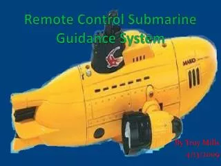
Remote Control Submarine Guidance System. By Troy Mills 4/13/2009. Project Background. The original concept was to use different color LED’s in order to control how the submarine would guide itself through a hoop. LED Color Key White -Rudder Down Blue -Rudder Up Red -Left turn

E N D
Remote Control Submarine Guidance System By Troy Mills 4/13/2009
Project Background • The original concept was to use different color LED’s in order to control how the submarine would guide itself through a hoop. • LED Color Key • White-Rudder Down • Blue-Rudder Up • Red-Left turn • Green-Right turn
Background Cont. • The cost of an LED color sensor was too much for the project budget. • Another means of guidance was to use LEDs, and to pulse them at different frequencies. • Due to energy consumption and acquiring sensors, Infrared LEDs were decided best for the job.
Understanding existing circuit • A very important part to the project was learning how to manipulate the existing circuit in the submarine to perform the tasks that would be directed by microcontrollers. • Lots of trial and error were use to understand where the output signals for the microcontrollers would be best placed. • Considering that the circuit compared to the RC car diagram that I had were very different, reverse engineering and pin layout research were done.
Probing and Results • By using the existing power that was used to supply the chip on the board many discoveries were made. • Probing the transistors to understand their function in the circuit helped me to narrow down exactly what makes operation and guidance possible. • An example of functions and their placement is show above.
Infrared Receivers • The receivers used to acknowledge the IR LEDs were similar to the type used in remotes for televisions. One set was 38KHz, and the other was to recognize 56KHz. • The IR sensors used for left and right motor control was designed to use 38KHz frequency. • The IR sensors used for up and down rudder control was designed to use 56KHz frequency. • These sensors turn the high frequency signal into one that can be used with code to determine an on position for the microcontrollers. • IR Sensors: 38KHz 56KHz
Infrared LED Lights • The pre-purchased package that is being use for the IR LED signal side is known as LED Blasters. This is a term used for Infrared LEDs that are often used in communication between remote controls and various electronics. • These IR transmitters have a 3.5mm headphone style jack that I will hook signal generators to for my working model presentation, allowing me to alter frequency at will.
Microcontroller Code • At this time no code has been written for the circuit nor has the board been designed. • The basic idea behind the code is standard digital programming. If one sensor gets a signal then the sub will move to better position itself to go through the hoop. • However when both sensors get a signal then the sub will remain or course and not change anything. • Through a single link between the microcontrollers the rudders will not act on their own unless microcontroller one shows activity.
Final Circuit Design • For the completion of this project the submarine will not be fully assembled but disassembled to show work and methods used along with easy recognition of components being used. • When the circuit is fully assembled it will be mounted underneath the submarine nose with the exception of the two up and down sensors. They will be located in convenient places depending upon optimal signal reading and analysis. • A final step will be to coat the board in wax, this will waterproof it and allow it to be more streamline with less drag.