Download
1 / 48
480 likes | 644 Vues
UNITEN. Dr. HABEEB HATTAB HABEEB Office: BN-Block, Level-3, Room-088 Email: hbuni61@yahoo.com Ext. No.: 7292. University TENAGA Nasional Lecturer: Dr. HABEEB ALANI . UNITEN. U niversity TENAGA National

E N D
UNITEN Dr. HABEEB HATTAB HABEEB Office: BN-Block, Level-3, Room-088 Email: hbuni61@yahoo.com Ext. No.: 7292 University TENAGA Nasional Lecturer: Dr. HABEEB ALANI
UNITEN University TENAGA National College Of EngineeringMechanical DepartmentAcademic Year – 2008-2009 Lecture Note University TENAGA Nasional Lecturer: Dr. HABEEB ALANI
UNITEN Computer Aided Manufacturing CAM University TENAGA Nasional Lecturer: Dr. HABEEB ALANI
CAM UNITEN Computer Aided Manufacturing Engineering Design University TENAGA Nasional Lecturer: Dr. HABEEB ALANI
Computer Aided Manufacturing UNITEN Engineering Design • Engineering design is the partial realization of designers concept. Today's a designer usually cannot directly transform a concept into a physical product. Instead, the designer conveys his idea to others through an alternative medium, such as an engineering drawing, and then the manufacturing engineer or machinist produces the design ( Fig. 2.1 ). University TENAGA Nasional Lecturer: Dr. HABEEB ALANI
Computer Aided Manufacturing UNITEN Development of designer idea Engineering Design Manufacture Idea • Operation plan • Sawing • Turning • Milling • Grinding • Inspection • Production • Design 1 2 3 4 ( Fig. 2.1 ) Evolution of product University TENAGA Nasional Lecturer: Dr. HABEEB ALANI
Computer Aided Manufacturing UNITEN Engineering design: Continued • Prior to the industrial revolution, if any one needed to use/ farmer tool for example, normally he will go to the blacksmith to fabricate this tool by using conventional methods. (why) because most tools were simple and did not require significant accuracy. Sometime blacksmith he don’t understand clearly, then the farmer will use the workshop wall as drawing paper to explain the real idea. University TENAGA Nasional Lecturer: Dr. HABEEB ALANI
Computer Aided Manufacturing UNITEN Engineering design: Continued Conventional Plough University TENAGA Nasional Lecturer: Dr. HABEEB ALANI
Computer Aided Manufacturing UNITEN Engineering design: Continued • Nowadays product requirements and designs became more complex, (Fig.2.2) University TENAGA Nasional Lecturer: Dr. HABEEB ALANI
Computer Aided Manufacturing UNITEN Engineering design: Continued (Fig. 2.2) University TENAGA Nasional Lecturer: Dr. HABEEB ALANI
Computer Aided Manufacturing UNITEN Engineering design: Continued • A picture became necessary to relate the information to others. Multiview drawings have long been adopted by engineers as the standard tool to represent a design. With such drawings, design information can be passed from the designer to others who are well trained in reading the design drawing. The designer should be build very good background to provide the engineers and technicians clear designs and completed. University TENAGA Nasional Lecturer: Dr. HABEEB ALANI
Computer Aided Manufacturing UNITEN Engineering design: Continued (Fig. 2.3) University TEAGA Nasional Lecturer: Dr. HABEEB ALANI
Computer Aided Manufacturing UNITEN Engineering design: Continued - To present theengineeringdrawing there are several methods: Drafting on paper with pen or pencil. Manual drafting is tedious. 1 Computer Aided Drafting CAD/ can improve drafting efficiency 2 University TENAGA Nasional Lecturer: Dr. HABEEB ALANI
CAD Benefits Computer Aided Manufacturing UNITEN Engineering design: Continued Design is stored in a computer and retrieved when needed 1 Built-in symbols, templates and tools 2 Drafting is done in 2D & 3D included all Engineering specifications 3 Media display is available ( Screen, printer, plotter, LCD) 4 University TENAGA Nasional Lecturer: Dr. HABEEB ALANI
Computer Aided Manufacturing UNITEN Design Drafting • Engineering drawingis an abstract universal language used to represent a designers idea to others. It is the most accepted media of communication in all phases of industrial and engineering work. University TENAGA Nasional Lecturer: Dr. HABEEB ALANI
Computer Aided Manufacturing UNITEN Design Drafting • Today pictorial drawings are still employed to supplement other design representations. The basic engineering drawing that uses orthographic projection provides a complete and unambiguous representation of a part or product . Fig. 2.4 illustrates the difference between perspective and orthographic projections. The perspective projection drawing in the figure uses two-point perspective. University TENAGA Nasional Lecturer: Dr. HABEEB ALANI
Computer Aided Manufacturing UNITEN Design Drafting Perspective and orthographic Projections Perspective Projection Orthographic Projection (Fig. 2.4) University TENAGA Nasional Lecturer: Dr. HABEEB ALANI
Computer Aided Manufacturing UNITEN Design Drafting • Most engineering drawings use isometric projection Fig. 2.5 . Isometric projection uses orthographic projection to each projection plane. The projection planes are oriented in such away that each of axes 120˚ apart. The reduction in length on each axes is the same. University TEAGA Nasional Lecturer: Dr. HABEEB ALANI
Computer Aided Manufacturing UNITEN Design Drafting (Fig. 2.5) University TENAGA Nasional Lecturer: Dr. HABEEB ALANI
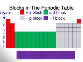
Computer Aided Manufacturing UNITEN Multiview drawing • In modern manufacturing industry, several types of drawings are acceptable. The standard Example: American standard (ANSI Y14), orISO standard (128, 129, 3098 etc,)) is still the multiview drawing Fig. 2.6 . University TENAGA Nasional Lecturer: Dr. HABEEB ALANI
Computer Aided Manufacturing UNITEN Multiview drawing (Fig. 2.6) University TENAGA Nasional Lecturer: Dr. HABEEB ALANI
UNITEN Related Documents • A multiview drawing usually contain two or three views…. (Front view, Top view, Side view) Multiview Drawing Front view Side view Top view University TENAGA Nasional Lecturer: Dr. HABEEB ALANI
Related Documents UNITEN UNITEN University TENAGA Nasional Lecturer: Dr. HABEEB ALANI
UNITEN Computer Aided Manufacturing • US & CANADA, the third-angle projection is the system used. Fig. 2.7, In the figure the four quadrant of the Z-Y plane is called: • I angle • II angle • III angle • IV angle University TENAGA Nasional Lecturer: Dr. HABEEB ALANI
UNITEN Computer Aided Manufacturing • For the third-angle projection, always • place the object in the 3rd quadrant and project the object in the three planes . Done by projection the object onto: • Frontal • Horizontal • Profile • …. planes (Fig. 2.7) University TENAGA Nasional Lecturer: Dr. HABEEB ALANI
UNITEN Computer Aided Manufacturing • The projection on the frontal X-Y plane is fixed, and the image is called the front view. The horizontal X-Y plane is rotated 90° clockwise on the X-axis,the result is a top view of the object. The profile Y-Z plane is rotated 90° clockwise about the Y-axis,to obtain a right-hand side view. University TENAGA Nasional Lecturer: Dr. HABEEB ALANI
Computer Aided Manufacturing UNITEN Partial View • When a symmetrical object is drafted / Two views are sufficient to present it. (Hence the third view is typically omitted)Fig. 2.9 . • Two View Drawing • of a Cap (Fig. 2.9) University TENAGA Nasional Lecturer: Dr. HABEEB ALANI
Computer Aided Manufacturing UNITEN Partial View • A partial view can be used to substitute for one of the two views Fig. 2.10 • Sectional and auxiliary views are also commonly used to present part detail. Sectional views, like that depicted Fig. 2.10 , are extremely useful in displaying the detailed design of a complicated internal configuration. (Fig. 2.10) University TENAGA Nasional Lecturer: Dr. HABEEB ALANI
Computer Aided Manufacturing Partial View UNITEN • When a major surface is inclined to all three projection planes, a translation of the picture is seen, a circle becomes an ellipse. In that case, an auxiliary plane that is parallel to the major surface, like that in Fig. 2.11 , can be used to display an undistorted view. (Fig. 2.11) University TENAGA Nasional Lecturer: Dr. HABEEB ALANI
Computer Aided Manufacturing UNITEN Dimensioning and Tolerancing • A drawing is expected to convey a complete description of every detail of a part. • Dimensions convey the required size. • Tolerances convey the required precision. • Dimensioning basic rules of American national Standards Institute (ANSI) as following: • Show enough dimensions. • State each dimension clearly. University TENAGA Nasional Lecturer: Dr. HABEEB ALANI
Computer Aided Manufacturing UNITEN Dimensioning and Tolerancing Cont……. • Show the dimensions between points, lines, or surfaces. • Select and arrange dimensions to avoid accumulations of tolerances. • Show each dimension only ones. • Specify the dimensions, In order to provide materials, parts, gauges etc… marks and labels. University TENAGA Nasional Lecturer: Dr. HABEEB ALANI
Computer Aided Manufacturing UNITEN Dimensioning and Tolerancing Cont……. Drawing information very important for who will use or read the drawing which affect to choice of the following: • Processes. • Fixtures. • Machine required. University TENAGA Nasional Lecturer: Dr. HABEEB ALANI
Computer Aided Manufacturing Dimensioning and Tolerancing Cont……. UNITEN - Dimensioning of circle use either dia. added to the end of the dimension value or the symbol ø added in front of the dimension value. For the specification of a radius an (R) is added in front of the dimension value. : Example --- University TENAGA Nasional Lecturer: Dr. HABEEB ALANI
Dimensioning Computer Aided Manufacturing UNITEN Main features of basic dimension: • Two extension lines. • Dimension line. • Dimension value. Dimension line Extension lines Dimension value University TENAGA Nasional Lecturer: Dr. HABEEB ALANI
Computer Aided Manufacturing Dimensioning UNITEN Basic rules of dimensioning: • Dimensions should be unambiguous and clearly. • Dimensions should be complete, with none missing. • There should be no redundancy; each dimension should be shown only once. Example --- University TENAGA Nasional Lecturer: Dr. HABEEB ALANI
Computer Aided Manufacturing UNITEN Dimension elements…. University TENAGA Nasional Lecturer: Dr. HABEEB ALANI
Computer Aided Manufacturing UNITEN Dimensions are used to show an object’s: 1. Overall: Width Depth Height 2. The actual size of features (rounds, fillets, holes, arcs, etc.) University TENAGA Nasional Lecturer: Dr. HABEEB ALANI
Computer Aided Manufacturing UNITEN 3. And where features are located such as centers, angles, etc. University TENAGA Nasional Lecturer: Dr. HABEEB ALANI
Computer Aided Manufacturing UNITEN Dimensions should be stacked in a “broken chain” format. “Breaking the Chain” refers to leaving out one dimension as shown above so that manufacturing tolerances are maintained. University TENAGA Nasional Lecturer: Dr. HABEEB ALANI
Computer Aided Manufacturing UNITEN -As a general rule…Stay off the object as much as possible. University TENAGA Nasional Lecturer: Dr. HABEEB ALANI
Computer Aided Manufacturing UNITEN -Extension lines can be shared and even broken to clarify crowded dimensions. University TENAGA Nasional Lecturer: Dr. HABEEB ALANI
Computer Aided Manufacturing UNITEN -Some features are dimensioned from their center lines. -The center line may also be used as an extension line. University TENAGA Nasional Lecturer: Dr. HABEEB ALANI
Computer Aided Manufacturing UNITEN - Leader with dimension for one hole used to show all cylinders (holes). - The leader should always be placed to penetrate the center of all round features. University TENAGA Nasional Lecturer: Dr. HABEEB ALANI
Computer Aided Manufacturing Features such as counterbores, countersinks and spot faces are all dimensioned using a leader.Note: Each of these features has a special dimensioning symbol that can be used to show: a. Diameter b. Shape c. Depth UNITEN University TENAGA Nasional Lecturer: Dr. HABEEB ALANI
Computer Aided Manufacturing - Arcs are always dimensioned as a radius. Full circles are dimensioned showing their diameter value. UNITEN University TENAGA Nasional Lecturer: Dr. HABEEB ALANI
Computer Aided Manufacturing - When dimensioning a part, always start with the inner-most dimensions and work to the outer-most values.Remember:Dimensions are used to show both the size and location of features. UNITEN University TENAGA Nasional Lecturer: Dr. HABEEB ALANI
Computer Aided Manufacturing - Always dimension features clear.- Drawing lines clearRemember….NEVER, NEVER, NEVER dimension to hidden lines! UNITEN University TENAGA Nasional Lecturer: Dr. HABEEB ALANI
UNITEN THANK YOU University TENAGA Nasional Lecturer: Dr. HABEEB ALANI