Chapter 1 Stress
Chapter 1 Stress. Mechanics of Materials. The study of the relationship between the external loads on a body and the intensity of the internal loads within the body. Equilibrium of a Deformable Body. External loads Surface forces

Chapter 1 Stress
E N D
Presentation Transcript
Mechanics of Materials • The study of the relationship between the external loads on a body and the intensity of the internal loads within the body
Equilibrium of a Deformable Body • External loads • Surface forces • Caused by the direct contact of one body with the surface of another • Concentrated force • Linear distributed load (if applied along a narrow area) • Body forces • Weight • Support reactions
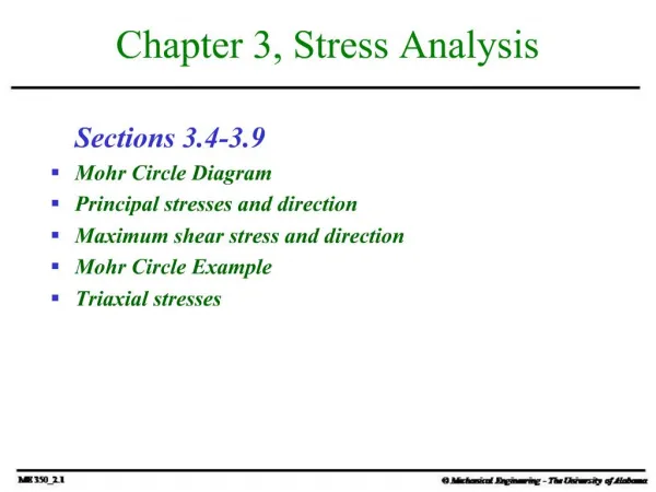
Equations of Equilibrium • In vector form • ∑ F = 0 • ∑ Mo = 0 • In 2-D scalar form • ∑ Fx = 0, ∑ Fy = 0 • ∑ MO = 0 • In 3-D scalar form • ∑ Fx = 0, ∑ Fy = 0, ∑ Fz = 0 • ∑ Mx = 0, ∑ My = 0, ∑ Mz = 0
Internal Resultant Loadings • Method of sections (recall approach to truss problems) • Imaginary section or "cut" is made through the region where the internal loadings are to be determined • The two parts of the body are separated • A free-body diagram of one of the parts is drawn • Equations of equilibrium are used to relate the external forces on the body to a resultant internal force and moment, FR and MRo • The actual internal loading is a distribution of forces as shown below (center) but can be represented by a force and moment (recall equivalent systems) • O is typically chosen at the centroid of the sectioned area
3-D Internal Resultant Loadings • Normal force, N • Acts perpendicular to the plane of the area • Develops when external loads tend to push or pull on the two segments of the body • Shear force, V • Lies in the plane of the area (usually determine two perpendicular components along coordinate axes, not shown in figure) • Develops when external loads tend to cause the two segments of the body to slide over one another • Torsional moment or torque, T • Develops when external loads tend to twist one segment of the body with respect to the other • Bending moment, M • Develops when external loads tend to bend the body about an axis lying within the plane of the area (usually determine two perpendicular components along coordinate axes, not shown in figure)
2-D (Coplanar) Internal Resultant Loadings • See pg 256 for M and V sign convention as specified for beam analysis • Problems, pg 17
Stress • Consider sectioned area to be divided into small areas such as ΔA • Assume a typical finite yet very small force ΔF acting on ΔA • Replace ΔF, by its three components, ΔFx, ΔFy, and ΔFZ (tangent and normal to the area respectively) • As ΔA approaches zero, so do ΔF and its components, but the quotient of the force and area will, in general, approach a finite limit • This quotient is called stress → it describes the intensity of the internal force on a specific plane (area) passing through a point
Normal and Shear Stress • The intensity of force (or force per unit area) acting normal to ΔA is defined as the normal stress, σ • If the normal force or stress "pulls" on the area element it is referred to as tensile stress, whereas if it "pushes" on the area element it is called compressive stress • The intensity of force (or force per unit area) acting tangent to ΔA is called shear stress, τ • Two subscripts are used for the shear stress components, the first subscript defines the plane on which the shear stress acts (as being perpendicular to the specified coordinate axis), and the second subscript refers to the direction of the shear stresses • In the SI system the units of stress are Pascals, Pa (one Pa is equivalent to one N/m2), kPa, MPa • In the English system the units of stress are psi (lb/in2), ksi (kip/in2), msi (million psi)
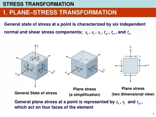
General State of Stress • The state of stress acting around the chosen point in the body
Average Normal Stress on an Axially Loaded Bar • Under the applied axial load it is assumed the bar undergoes uniform deformation • The bar remains straight and the cross section remains flat or plane during deformation • Regions of the bar near the ends where the external loads are applied can cause localized distortions and are not considered here • For the bar to undergo uniform deformation • The load, P, must be applied along the centroidal axis of the cross section • The material must be homogenous (same physical and mechanical properties throughout its volume) and isotropic (same properties in all directions) • If the bar is subjected to a constant uniform deformation, then this deformation is the result of a constant normal stress, σ
Equilibrium of a Volume Element • Only a normal stress exists on any volume element located at each point on the cross section of an axially loaded bar • Considering equation(s) of force equilibrium
Average Shear Stress • The average shear stress distributed over each sectioned area that develops the shear force shown is defined by, • τavg is in the same direction as V
Equilibrium of a Volume Element • A volume element of material taken at a point located on the surface of any sectioned area on which the average shear stress acts • In order to satisfy equilibrium all four shear stresses must have equal magnitude and be directed either toward or away from each other at opposite edges of the element (referred to as the complementary property of shear)
Lap Joints • Single lap joint or lap joint (single shear connection) • Members are thin • Nut not tightened to any great extent so friction between the members can be neglected • Double lap joint (double shear connection)
Other Loading on Mechanically Fastened Lap Joints • Bearing , net tension , shear tearout • Typically bearing strength, tensile strength and shear strength of a material all differ • Problems, pg 39
Factor of Safety and Allowable Stress • The factor of safety (F.S.) is a ratio of the failure load divided by the allowable load, F.S. = Ffail/Fallow or since the load is linearly proportional to stress, F.S. = σfail/σallow or F.S. = τfail/τallow • F.S. must be greater than one to avoid the potential for failure • Specific values depend on the types of materials to be used and the intended purpose of the structure or machine • Margin of safety is used in the aerospace industry, M.S. = F.S. -1
Sizing of Simple Connections • Simple connections can be designed/sized by using A=P/σallow or A=P/τallow • Area of a tension member • Area of a connector subjected to shear (properties of bolt materials)
Sizing of Simple Connections (continued) • Area to resist bearing • Area to resist shear caused by axial load • Problems, pg 55