Download
1 / 21
260 likes | 526 Vues
Delay and Power analysis of carbon nanotube interconnects for VLSI Application. Author’s Name : Mayank Kumar Rai ,Love Gupta , S.Sarkar. Presented By: Love Gupta Dept. of Electronics & Instrumentation. INDEX. Introduction Dimensions of interconnect Materials for Interconnect

E N D
Delay and Power analysis of carbon nanotube interconnects for VLSI Application Author’s Name : Mayank Kumar Rai ,Love Gupta ,S.Sarkar Presented By: Love Gupta Dept. of Electronics & Instrumentation
INDEX Introduction Dimensions of interconnect Materials for Interconnect Drawbacks of Copper SWCNT – Introduction & Advantages R,L,C calculation Simulation of Results Conclusion References
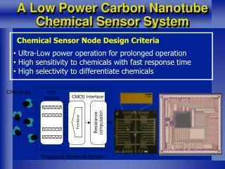
INTRODUCTION • The wire linking transistors together is called interconnect The interconnect has become a critical determiner of circuit performance in the deep sub-micron regime. As the technology size is decreasing the length of global interconnections is increasing , which increases the delay. K. Banerjee, et al., AMC, 2005
Dimensions of interconnect • ρ= resistivity (m) • R = sheet resistance ( /) • Pitch = w + s • Aspect ratio: AR = t/w
Methods For Improving Propagation Delay • By inserting buffers to drive large capacitive loads • But single buffer is not a good solution , so a number of buffers • need to be inserted at regular intervals of distance in interconnect , • which are termed as repeaters. Repeater can be of different types • Uniform minimum sized • Optimum sized • Tapered cascaded buffers
MATERIALS • Aluminum and copper are the two conductive materials currently used for on chip interconnections. • The main limitations of the aluminum-based process is its higher resistivity, compared to copper. • The manufacturing difficulties related to Cu interconnections make it a more expensive than Al based interconnections, but this extra cost can be compensated by better performance.
DRAWBACKS OF COPPER • Increasing resistivity due to : • The presence of highly resistive • diffusion barrier layer • Surface scattering • Enhanced grain boundary scattering.
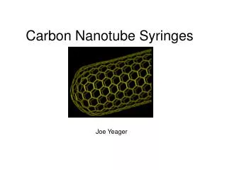
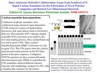
What is a Carbon Nanotube? What is a Carbon Nanotube? What is a Carbon Nanotube? What is a Carbon Nanotube? CNT is a tubular form of carbon with diameter as small as 1nm. Length: few nm to microns. CNT is configurationally equivalent to a two dimensional graphene sheet rolled into a tube. Types of CNTs : • Single Wall CNT (SWCNT) • Only one shell • Diameter ranging from 0.4nm to 4nm • Multiple Wall CNT (MWCNT) http://www.nature.com Having several concentric shells and diameter ranging from several nanometers to tens of nanometers.
ADVANTAGES OF SWCNT CNTs have long MFPs (of the order of several micrometers) Which provide low resistivity and possible ballistic transport in short length interconnects. CNTs exhibit extraordinary strength and unique electrical properties, and are efficient conductors of heat and have large current carrying capacity.
EQUIVALENT CIRCUIT MODEL FOR AN ISOLATED SWCNT • RF=h/4e2 ~6.45K • RCNT=(h/4e2)L/L0 Diffusive transport (L>> L0) Total resistance of CNTs a) Fundamental one-dimensional system (cnt) contact resistance, b) scattering resistance and c) imperfect metal nano tube contact resistance Ballistic transport (L<L0) Where L0 is the MFP CAPACITANCE: a) Electrostatic capacitance (CE ) b) quantum capacitance (CQ ) , CQ=2e2/h~100aF/um ~30aF/um =
a CNT has four conducting channels so the effective quantum capacitance resulting from four parallel capacitances CQ is given by 4 . Total Inductance : Magnetic Inductance Kinetic Inductance LM= Lk= = 16nH/m = 8x10⁵m/s
Bundle of SWCNTs • Resistance of a CNT-Bundle R bundle=R isolated/n CNT Capacitance of a CNT-bundle Where is 4 times of CQ. Inductance of CNT-bundle L< L0CNTwith L bundle=(LM+Lk/4)/nCNTand (b) L>> L0CNTwith L bundle=LM/nCNT.
Spice Simulation Results Delay of Copper and CNT at global and intermediate lengths(Tech:32nm)
Voltage-scaled repeaters for long interconnections We use repeaters to reduce delay, but they increases the power dissipation in VLSI circuits ,so by using voltage scaled repeaters we can considerably reduce power dissipation.
Voltage scaling Power vsVdd(Tech:32nm)
Conclusion • At local level Cu Interconnect gives better performances than a bundle of SWCNT. • Where as a bundle of SWCNT has better efficiency at intermediate level and Global level. • Where as, power decreases with lower value of Vdd and increases with increase in number of repeaters due to higher value of capacitance. For better performance power supply should be balance, with voltage scaled repeaters.
REFERENCES [1] W. Steinhogl, G. Schindler, G. Steinlesberger, M. Traving, and M. Engelhardt, “Comprehensive study of the resistivity of copper wires with lateral dimensions of 100nm and smaller,” Journal of Applied Physics, vol. 97,pp. 5186-5189, 2005. [2] P. L. McEuen, M. S. Fuhrer, and H. K. Park, “Single-walled carbon nanotube electronics,” IEEE Trans. Nanotechnology, vol. 1, pp. 78-85, 2002. [3] F. Kreupl, et al., “Carbon Nanotubes in Interconnect Applications,” Microelectronic Engineering, vol.64 pp. 399-408, 2002. [4] J. Li, et al., "Bottom-up Approach for Carbon Nanotube Interconnects," Applied Physics Letters, Vol. 82, pp. 2491-2493, April 2003. [5] A. Thess, et al., “Crystalline Ropes of Metallic Carbon Nanotubes”, Science, Vol. 273, pp. 483-487, 1996. [6] J. Li, et al., "Carbon Nanotube Interconnects: A Process Solution", IEEE Intl. Interconnect Tech. Conf. pp. 271-272, 2003. [7] M. Nihei, et al., “Carbon Nanotube Vias for Future LSI Interconnects,”IEEE Intl Interconnect Tech Conf , pp.251-253, 2004. [8] P. J. Burke, “Luttinger Liquid Theory as a Model of the Gigahertz Electrical Properties of Carbon Nanotubes”, IEEETrans. Nanotechnology, Vol. 1, pp.129-144, 2002. [9] P. L. McEuen, et al., “Single-Walled Carbon Nanotube Electronics,” IEEE Trans. Nanotechnology, Vol. 1, pp. 78-85, 2002. [10] N. Srivastava and K. Banerjee, “Performance analysis of carbon nanotube interconnects for VLSI applications,” IEEE/ACM Intl. Conf. on ICCAD , pp. 383-390, 2005.
Ballistic transport (L<L0) Diffusive transport (L>> L0)
MODEL PDISTRIBUTED MODEL