Download
1 / 30
300 likes | 329 Vues
Learn about the innovative Power StarTM concept, combining old and new technologies to simplify space-based solar power structures, eliminate moving parts, and ensure dynamic stability. Explore the unique features and benefits of this cutting-edge approach.

E N D
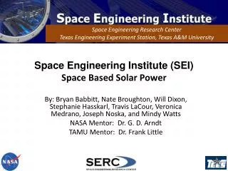
Global Prosperity Through Space-Based Solar PowerThe Power StarTM Concept Prof. David Hyland Mech Aero – 2014 Hilton Philadelphia Airport Hotel September 8 -10, 2014
Power StarTM Also contributed at the International Conference on SBSP, Kobe, Japan, April 2014 So new it’s scarcely noticed, So old it’s almost forgotten
Background • All previous SPS concepts • Involve gigantic, complex, articulated structures • Contain numerous, perhaps 1000s, of moving parts • Require numerous launches • Require on-orbit fabrication/construction, usually robotic • Involve serious dynamic stability issues • Power StarTM combines very new and very old technologies to obtain: • The simplest possible structure • No moving parts (except electrons and photons) • One launch vehicle (A one-km system can fit into several existing vehicles) • No on-orbit construction • Inherent dynamic stability and robustness
The New The next slide shows the new technology. Solar collectors and microwave transmitters can be printed on a thin fabric. The collectors and transmitters are combined in modules called “collectennas”TM.
Transmitter Solar cell Solar cell Power connectors Conductive coating (ground) Substrate layer The New Printed Patch Antennae Printed Solar Arrays Solar-Microwave Fabric
The Old The next slide shows the Echo satellite technology. The satellite is launched in a small container, then inflated to form a large, hollow sphere.
Fabrication of the Power StarTM Solar-Microwave FabricTM is produced in oval strips The strips are joined to make the sphere
Meridonial Sectors Spherical Balloon
Deployment The Power Star is folded in a small container that is launched in one launch vehicle. The container opens and the balloon is inflated
Negligible final angular velocity Packaging and Deployment
The Basic Module • The sphere is covered with collectennaTM modules arranged in a randomized pattern • This avoids grating lobes • Ground beacons give the desired power distribution on the ground • Each collectennaTM module senses the ground beacon radiation, amplifies it, and transmits it in reverse time. • This gives the best fit to the desired power distribution • Multiple beams can be formed and shaped
In each patch antenna: • Local microprocessor records beacon radiation waveform • Amplifies waveform and emits it back in reverse time. • Power optimally matches desired power distribution on the ground. Transmitter Solar cell Solar cell Substrate layer transceivers Exterior surface Copper grid Power connector Microwave Power Rectenna Beacons Random Tessellation to prevent grating lobes Beacon Radiation Printed microwave transmitter elements Printed solar array elements No moving parts!
Fundamental Power Shaping Concept The next two charts illustrate the power shaping concept as first devised for acoustics
The very same time-reversal principle has been applied to acoustics. See Scientific American, November 1999.
Illustration of Power Shaping The collectennaTM operations are simultaneous. But we illustrate one step at a time. The next chart shows a simulation of a flat phased array receiving radiation from two beacons on the ground.
Recording the beacon signals, then amplifying them and playing them back in reverse time occur concurrently. To simplify the explanation, we illustrate these steps separately. First, consider the beacon propagation… On this plane we have two point sources representing the beacons When the beacon radiation reaches the line segment representing the phased array, each point on the line records the wave-form that it sees. Each pixel on this line segment is a separate recorder
Illustration of Power Shaping (Continued) The next chart shows the transmission step Two spots of concentrated power, centered on the beacon locations are created. If the phased array were infinitely large, the two point sources would be matched exactly
Now turn off the beacon and let each pixel on the line segment re-transmit the wave-form it recorded - but in reverse time… Note the converging wave fronts The amplitude on the ground plane has two concentrations centered on the beacons. If the transmitting array were infinite in extent, these would be point concentrations. Each pixel on this line segment transmits the recorded signal in reverse time
A Better Shape The next chart shows that a spherical phased array would work as well. A sphere gives flexibility – collect power from any direction, transmit power in any direction. No moving parts needed.
Localized Power Distribution Solar radiation Beacon radiation Interior surface printed with -wave receiver/transmitters (possibly shorter wavelengths)
Power Distribution - Summary • Each antenna transmits only if the beacon(s) radiation is received. • Each transmitting antenna draws power from • Solar cells in its immediate vicinity (within a few centimeters), or • Through the thickness of the “skin” from receivers on the inner surface of the skin. • Power transmission through the skin traverses a few centimeters or less. Each transmitter receives just a few Watts No high voltages, no large wires • Power distribution to each antenna is local – there is no need for a complex power management system. • Strictly local architecture means robustness against partial damage!
Dynamic Stability of Power StarTM The next chart shows that surface errors or damage can be compensated solely by electronic means. There is no control/structure interaction – The system is inherently stable
Error Compensation is purely electronic. There is no control/structure Interaction Undistorted radiation pattern Phased Array Gain Disturbances System Dynamics Array element deformation/vibration Sensor measurements of array element position errors Electronic phase adjustment Actuator forces and torques Actuator dynamics Dynamic feedback control Actuator commands
The Overall Concept The next chart shows a sketch of the overall concept We also list the important features
Transmitter Random Tessellation to prevent grating lobes Solar cell Solar cell Substrate layer transceivers Printed solar array elements Printed microwave transmitter elements Summary Sketch of the Concept Unique features: • Its structure is extremely simple and can be fit into many launch vehicle payload envelopes. • It can gather solar power from any angle and beam power in any direction (s) without slewing or structural deformation. • It has no moving parts. • It can optimally approximate any desired field distribution on the ground. • It requires no in-space assembly or construction • It has no control/structure feedback so the system is guaranteed dynamically stable. • The operation of the phased array is adaptive so that even if severely damaged, the system can retain some level of useful performance. ~ 1 km w
Conclusion Power StarTM is launched as a small seed, then grows to a mighty sphere. Although large, it uses the independent action of each small part. It uses the very new to give new life to an old but beautiful satellite design. (The Latin means: “Nature is greatest in the smallest things”)
Power Star Natura in Minima Maxima