Steam Condenser I
Mechanical Engineering Department ME332 Operation and Management of Power Plants Prof. Osama A El Masry. Steam Condenser I. Prof. Osama El Masry. Direct Contact Condenser. This type of condenser is suitable where conditions permit condensation of exhaust

Steam Condenser I
E N D
Presentation Transcript
Mechanical Engineering Department ME332 Operation and Management of Power Plants Prof. Osama A El Masry Steam Condenser I Prof. Osama El Masry
Direct Contact Condenser This type of condenser is suitable where conditions permit condensation of exhaust steam by direct contact with the cooling water. The vacuum is created in the chamber by an air ejector. The cooling water is sprayed into the chamber an the fine spray contacts the steam. The steam condenses and falls to the bottom of the condenser chamber with the injection water. The condensed steam and injection water is withdrawn using a centrifugal extraction pump
Barometric Condenser Barometric Counter-Current Condensers have no moving parts. Little maintenance is required and provision can be made for internal inspection of the unit. Because of the barometric leg, no water removal pump is required
Barometric Condenser Multi-Jet Barometric Condensers are generally employed where low cost water is available in ample quantity. It is the simplest design of all barometric condensers, and requires no auxiliary air pump or pre-cooler. - Recommended for operation under fairly constant loads where there is relatively little air leakage, and where water is not too scarce and does not need to be recirculated.
Jet-Type Condenser Multi-Jet Spray Type Barometric Condensers are generally employed where large capacities are required and where wide fluctuations in water temperature or steam load occur.
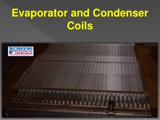
Surface Condensers Surface condensers are the most commonly used condensers in modern power plants. The exhaust steam from the turbine flows on the shell side (under vacuum) of the condenser, while the plant’s circulating water flows in the tube side.
Surface Condensers The source of the circulating water can be either a closed-loop (i.e. cooling tower, spray pond, etc.) or once through (i.e. from a lake, ocean, or river). The condensed steam from the turbine, called condensate, is collected in the bottom of the condenser, which is called a hot well. The condensate is then pumped back to the steam generator to repeat the cycle.
Surface Condensers Surface condensers are basically a shell and tube heat exchanger consisting of water boxes for directing the flow of cooling water to and from horizontal tubes. The tubes are sealed into fixed tube sheets at each end and are supported at intermediate points along the length of the tubes by tube support plates. Numerous tubes present a relatively large heat transfer and condensing surface to the steam. During operation at a very high vacuum, only a few kgs of steam are contained in the steam space and in contact with the large and relatively cold condensing surface at any one instant.
surface condenser have improved by cutting down the bundle to half and making two smaller bundles beside each others to overcome the high pressure drop problem . • Baffles are used to help the steam distribution and accelerate condensation rate • The shell is fabricated from carbon steel plates and is stiffened as needed to provide rigidity for the shell. • Intermediate plates are installed to serve as baffle plates that provide the desired flow path of the condensing steam. The plates also provide support that help prevent sagging of long tube lengths. • At the bottom of the shell, where the condensate collects, an outlet is installed. In some designs, a sump (often referred to as the hot well) is provided. Condensate is pumped from the outlet or the hot well for reuse as boiler feed water.
Shell Outlet Channel Inlet ChannelOutlet Shell Outlet SINGLE SEGMENTAL TRANVERSE BAFFLES
Tube sheets of sufficient thickness usually made of stainless steel is provided, with holes for the tubes to be inserted and rolled. This is to avoid eddies at the inlet of each tube giving rise to erosion, and to reduce flow friction. To take care of length wise expansion of tubes some designs have expansion joint between the shell and the tube sheet allowing the latter to move longitudinally. • Size: modern condensers use 7/8 or 1.0 in tube of 18 gauge thickness • Condensers may have up to four passes; one and two pass condensers are the most common. In a single pass condenser, the cooling water makes one passage from end to end, through the tubes. Single pass condensers have an inlet waterbox on one end and an outlet water box on the other end. Two pass condensers have the cooling water inlet and outlet on the same water box at one end of the condenser, with a return water box at the other end.
A single pass condenser is commonly used where the water is supplied from natural sources such as rivers or oceans. If the source of circulating water is at all limited, a two pass condenser will probably be the best selection since a single pass condenser requires more cooling water per square foot of condenser surface and per kilowatt of electrical generation. Usually, a two pass condenser is used with cooling towers or a cooling lake. • Waterboxes: The tube sheet at each end with tube ends rolled, for each end of the condenser is closed by a fabricated box cover known as a waterbox, with flanged connection to the tube sheet or condenser shell. The waterbox is usually provided with man holes on hinged covers to allow inspection and cleaning. These waterboxes on inlet side will also have flanged connections for cooling water inlet butterfly valves, small vent pipe with hand valve for air venting at higher level, and hand operated drain valve at bottom to drain the waterbox for maintenance. Similarly on the outlet waterbox the cooling water connection will have large flanges, butterfly valves, vent connection also at higher level and drain connections at lower level.
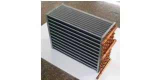
Hood or Plenum Fan Ring Fan Inlet Nozzles Return Headers Inlet Headers Outlet Headers Outlet Nozzles Tube Bundle Drive Assembly Supports Air Cooled Condensers
Dry Cooling • Steam ducted to air-cooled condenser • Condensation inside finned tubes - analogous to automobile radiator • Cold water approaches dry bulb temperature
Steam Condensers Water Cooled Condensers Air Cooled Condensers Internal Surfaces External Surfaces
Tube Fouling Deposition or Particulates Scaling or Crystallization Corrosion Products Microbiological Debris
Deposition or Particulates Are fine particulates that settles on the tube surface due to gravity under low flow condition. Natural sediment Crystalline solids Bio-growth Coal dust
Scaling or Crystallization Fouling • Scale occurs when the saturation point of dissolved constituents in the • cooling water is exceeded. • Scale can provide sites for local under scale corrosion Pitting under scale in stainless steel tube
Debris Caused by any substance whose size is close to, or greater than, tube internal diameter. Examples : • Rocks • Cooling tower materials ( Plastic fill , wood ) • Large pieces of rusted steel • Aquatic animals ( Small fishes ) • Any other substance that enters the circulating water can obstruct • cooling water flow
Tubewall Deposit Layer Film 800ºF 785ºF Tube Metal Temperature 766ºF Inside Tube Temperature 730ºF Film Temperature 700ºF Fluid 600ºF 520ºF Bulk Fluid Temperature 500ºF Temperature Profile in Heat Transfer
Cleaning interior surfaces of tubes Chemical Mechanical Off Line Cleaning On Line Cleaning
Chemical treatment • Several chemicals, often in combination, are used to control condenser tube fouling. Chemical treatment methods : • PH control ( lowering PH to 5.8 or 4 ) • Scale inhibitors • Corrosion inhibitors ( Zinc & phosphates for carbon steel )
Utilized for recirculating cleaning system because of : 1) The concentration of dissolved constituents is significant, increasing the threat of scaling and corrosion. 2) Once-through cooling systems often discharge directly into a river, lake, or ocean where chemicals concentrations are restricted.
Disadvantages of chemical treatment: • Expensive. • Job duration is excessive. • Subsequent disposal of the chemicals requires serious consideration due to potential environmental hazard.
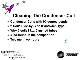
Mechanical cleaning Off line cleaning Hydrodrilling High Pressure Water Molded Plastic Cleaners ( Pigs ) Brushes Metal Scrapers
High pressure water : • The water is directed in a high pressure towards the tubes. • Disadvantages: • The time taken to clean a condenser can become extended. • Could damage tube sheet or tube coatings.
Pigs • They are molded plastic cleaners . • Quit popular for softest types of deposits such as mud , silt and microbiological fouling Plastic tube cleaners
Brushes • Used to remove micro / macro fouling, soft organic scales, some corrosion by-products. • Useful for cleaning tubes with thin wall metal inserts or epoxy type coatings.
Metal Scrapers • Used for harder types of deposits such as calcium carbonate. • The blades are mounted on a spindle. • One end of the spindle is a serrated plastic disc that allows a jet of water to propel the cleaners through the tube.
How does this technique work? • Spring loaded tube cleaner (Bullets) are shot through fouled Condenser tubes using specially designed water guns at 1.5-2.5 MPa water pressure with velocities 3-6 m/s. • Tube cleaners exit at the end of the condensers, hitting a collection screen hung at the other end. • These cleaners are collected, cleaned and used again. Normally a bullet can be used 10 to 15 times.
Hydrodrilling • Used to remove difficult deposits from the inside of tubes . • Hard deposits such as ( Calcium, sulfur and oxides). • Could be used on-site therefore eliminating the need for bundles to • be sent off-site for cleaning treatments. • Polishes tube internal diameter to as-new condition.
Advantages of Hydrodrilling • It uses a small a volume of water (2 to 3 GPM at 200 to 300 PSI) that is filtered and recycled through a booster pump. • Greater heat transfer efficiency. • Less scheduled cleaning time and cost. Cleaning effects for a calcium carbonate scale: Before After
In-Line Mechanical Cleaning • The tube cleaning system consists of: • Balls that are slightly larger in diameter than the tubes. • Ball injection nozzle. • Ball strainer. • Ball recirculating pump. • Ball collector.
Sponged balls Ball Strainer
External surfaces fouling Dirt, dust & debris Insects & bird carcasses Pollen & Leaves
Cleaning External Tubes Surfaces Fire hose High pressure handlance Automated cleaning machine
Fire hose • Uses low pressurized water but with high volume flow rates. • Has low washing effect. Advantages: • The galvanized surfaces of the tubes and fins are not damaged by this method. Disadvantages: • Unit must be taken out of service and scaffolding erected. • Improvements are quite small, since only a portion of debris is removed, remainder being compacted between tube fins
High pressure handlance • Low water consumption and a high water pressure • Latter can damage galvanized surfaces and/or snap off fins • Unit must be taken out of service and scaffolding erected • Again, improvements are quite small since only portion of debris is • removed, remainder being compacted between tube fins
Automated Cleaning Machine • 60 GPM at 1,000-2,000 psi water pressure avoids fin and tube surface • damage. • Adjustable nozzle design, distance from surface and jet energy. • Water contains no additives. • Fouling removed effectively and uniformly. • No need to shut unit down or erect scaffolding. • Nozzle beam optimally matched to tube bundle geometry with a constant jet angle.
Forms of Automated Cleaning Machine Permanently installed system Semi-automatic system Portable service unit
Permanently installed system The system is supplied for each side of the ACC & controlled automatically
Semi-automatic system • The guide rails are permanently installed. • The nozzle beam carriage being moved from section to section by the labour.