Download
1 / 39
600 likes | 1.4k Vues
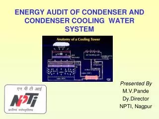
ENERGY AUDIT OF CONDENSER AND CONDENSER COOLING WATER SYSTEM. Presented By M.V.Pande Dy.Director NPTI, Nagpur. Hot Water. Cooling Tower. Condenser. Air. Air. Cooled Water. Make-up Water. Background. Condenser:

E N D
ENERGY AUDIT OF CONDENSER AND CONDENSER COOLING WATER SYSTEM Presented By M.V.Pande Dy.Director NPTI, Nagpur
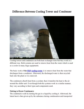
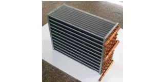
Hot Water Cooling Tower Condenser Air Air Cooled Water Make-up Water Background Condenser: The condenser is the most important component of the turbine cycle that affects the turbine heat rate. The function of the condenser is to condense exhaust steam from the steam turbine by rejecting the heat of evaporation to the cooling water passing through the condenser. Generally, twin shell- double pass- surface type condensers are employed for higher capacity units Hot Water CW Pump
Background • Cooling towers: Different types of cooling towers are used in the power plants depending upon the location, size, infrastructure and water resources etc. • Close cycle – wet cooling systems: • -Induced draft • Forced draft • - Natural draftcooling towers
Background Cooling water pumps: • Circulating water pumps supply cooling water at the required flow rate and pressure to the power plant condenser and the plant auxiliary cooling water heat exchangers. These pumps are required to operate economically and reliably over the life of the plant. • For once through systems, vertical wet pit pumps are in common usage. • For re-circulating cooling systems, vertical wet pit and horizontal dry pit are used about equally, with occasional use of vertical dry pit pumps.
Steps Involved in Energy Audit The major energy consuming equipments in the CW systems are: • Cooling towers and fans • Cooling water pumps • Make up water pumps • Condensers The steps involved in conducting energy audit of cooling water and cooling tower are: • Data collection • Observations and Analysis • Exploration for energy conservation measures • Report preparation
Data Collection Specifications of cooling towers:
Data Collection Specifications of cooling towers- contd…:
Specification of water pumps and motors Specification of water pumps and motors:
Data Collection Specification of water pumps and motors- contd…: Rated kW of the pump
Data Collection- Other Information • Performance characteristics of all pumps and motors • Compile design, P. G. Test, previous best and last energy audit value with respect to cooling tower and cooling water system along with the condensers • If the pumps are operated in parallel then it is advised to collect the performance curve for the parallel operation • Schematic diagram of Water pumping network (which depict the source, pumps in operation & stand by, line sizes and users) • Water and pressure equipments at the users as per the design requirements • Brief description of the system with the key specifications in which pumps are used (for example, if pumps are used for supplying water to condenser, then add a brief write up about the cooling water system)
Data Collection- Condenser Specifications • Heat load considered for design • Design inlet cooling water temperature/ Design TTD • Cleanliness factor/ Cooling water temperature raise • Condenser back pressure • Cooling water flow/ Cooling water side pressure drop • No of cooling water pass/ Total heat transfer area • No. of tubes - Condensing zone - Air cooling zone • Tube dimensions: - Tube OD x thickness - Length of tube • Tube material: - Condensing zone - Air cooling zone • Water box design pressure
Instruments Required • Power Analyzer: Used for measuring electrical parameters of motors such as kW, kVA, pf, V, A and Hz • Temperature Indicator & Probe • Pressure Gauge: To measure operating pressure and pressure drop in the system • Stroboscope: To measure the speed of the driven equipment and motor • Ultra sonic flow meter or online flow meter • Sling hygrometer or digital hygrometer • Anemometer • In addition to the above calibrated online instruments can be used • PH meter
Measurements & Observation • Energy consumption pattern of pumps and cooling tower fans • Motor electrical parameters (kW, kVA, Pf, A, V, Hz, THD) for pumps and cooling tower fans • Pump operating parameters to be measured/monitored for each pump are: - Discharge, - Head (suction & discharge) - Valve position – Temperature - Load variation, Power parameters of pumps - Pumps operating hours and operating schedule • Pressure drop in the system (between discharge and user point) • Pressure drop and temperatures across the users (heat exchangers, condensers, etc) • Cooling water flow rate to users - Pump /Motor speed • Actual pressure at the user end • User area pressure of operation and requirement
Measurements & Observation • Cooling tower parameters to be monitored • Inlet temperature • Outlet temperature • Dry bulb temperature • Wet bulb temperature or relative humidity • Water flow to cooling tower • Air flow rate of cooling tower • Range, oC • L/G ratio • Approach, oC • Fan speed, rpm • Fan power consumption (kW/cell)
Observations and Analysis • System familiarization and operational details • Energy consumption Pattern • The energy consumption of cooling water : kWh/day and associated system • Total auxiliary power consumption : kWh/Day
Operating Efficiency and Performance Evaluation of the Pumps • Water flow rate and pressure of pumps / headers • Velocity in the main headers and pumps and major lines (to verify adequacy of line sizes) • Power consumption of pumps (for estimating the operating efficiency of the pumps) • Monitor present flow control system and frequency of control valve variation if any (for application of variable speed drives) • Fill up the following data sheet for every pump for comparison with the design / PG test values
Operating Efficiency and Performance Evaluation of the Pumps
Operating Efficiency and Performance Evaluation of the Pumps
Investigations & Recommendations • Compare the actual values with the design / performance test values if any deviation is found, investigate for the contributing factors and arrive at appropriate suggestions • The investigations for abnormality are to be carried out for problems. Enlist scope of improvement with extensive physical checks / observations. • Based on the actual operating parameters, enlist recommendations for action to be taken for improvement, if applicable such as • Replacement of pumps/ Impeller replacement/ trimming • Variable speed drive application, etc • Compare the specific energy consumption with similar type of pumps and latest energy efficient pumps • Cost analysis with savings potential for taking improvement measures.
Flow Distribution • Measure the flow at the individual pump discharge side, main header, at • the users (for the major and large users) along with the pressure and • velocity. Depict these values in schematic diagram • Ensure Line adequacy by measuring the velocity in the major pipe lines • Pressure drop in the distribution network • Specific water flow rate
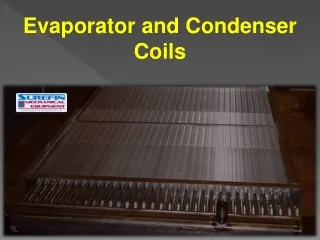
Performance of Condensers • Parameters for condenser performance
Performance of Condensers • Parameters for condenser performance- contd…
Performance of Condensers • The following needs to be computed: 1. Condenser heat load = Q x T x Cp 2. Calculated condenser vacuum = Atmospheric pressure – Condenser back-pressure 3. Deviation in condenser vacuum = Expected condenser vacuum - Measured condenser vacuum 4. Condenser TTD = Saturation temperature – Cooling water outlet temperature
Performance of Condensers 5. Condenser Effectiveness = Rise in cooling water temperature Saturation temperature - Cooling water inlet temperature 6. Condenser heat duty in kcal/h = Heat added by main steam + heat added by reheater + heat added by SH attemperation + heat added by RH attemperation + heat added by BFP - 860 x (Pgen + Pgen losses + heat loss due to radiation) 7. Condenser tube velocity (m/s) = Cooling water flow rate (m3/h) x 106 3600 x tube area (mm2) x ( no. of tubes per pass - no. of tubes plugged per pass )
Tout - Tin LMTD = Tsat -Tin Ln Tsat - Tout Tube velocity during test Tube velocity design 0.50 ( ) fw = Condenser design duty Condenser duty during test ( ) fq = Performance of Condensers 8. Determination of actual LMTD 9. LMTD expected = LMTD test x ft x fw x fq ft: Correction for cooling water inlet temperature 0.25 ( Saturation Temperature during test – LMTD during test Saturation Temperature design – LMTD design ) ft= fw: correction for water flow rate fq: correction for cooling water heat load
Observations During Condenser Energy Audit • Tubes in operation Vs total installed • Cleaning system operation • Filtering system for cooling water • Regular monitoring system for performance • Comparison of LMTD, TTD, heat load, condenser vacuum, flow, temperatures, pressures with design / PG test- arriving the factors causing deviation • Modifications carried out in the recent past • Cooling water flow • Pressure drop on water side and choking • Affect of present performance of cooling tower • Accurate metering of vacuum • Absolute back pressure deviation from expected value • Sub cooling of air –steam mixture and condensate • Circulation water temperature raise • Effectiveness of cleaning the tubes • Circulating water velocity in tubes
Performance of Cooling Towers • While conducting the cooling tower, visual observations need to be made with respect to: • Adequate water level in the trough • Cross flow air from other cooling towers (which are under • maintenance) • Nozzle condition and operation • Fill condition • Change of blade angles during change of seasons • The CT airflow shall be measured using an anemometer and compared with calculated airflow derived from fan characteristic curves of CT fans with actual power measurements. • Calculate range, approach, L/G (Liquid to gas) ratio and effectiveness for design and operating conditions for each tower
Range x 100 ( range + approach ) Effectiveness % = Fan actual airflow (Nm3) / cell = 1/3 Fan rated airflow (Nm3) / h x ( Fan input kW actual ) ( Fan input rated ) 1/3 Performance of Cooling Towers 1. C.T. Range = Water inlet temperature – Water outlet temp. 2. C.T. Approach = Water outlet temperature – Wet bulb temp. 3. 4. 5. Air mass flow / cell = flow x density of air
CW flow (m3/ h) x CT range in 0C 675 5. Evaporation losses = Evaporation losses (COC – 1) 6. Makeup water consumption = Performance of Cooling Towers • The above readings may be taken on daily basis for three days on different atmospheric conditions say during mid summer, winter & monsoon period. Once in the mid day and once in the mid night time and a record duly maintained. • Collect unit load (MW), frequency, and condenser vacuum condition while taking the cooling tower measurement
Performance of Cooling Towers • Power consumption of CT fans • Exploration of Energy Conservation Possibilities: • Condenser • Possibility of Improvement in condenser vacuum • Turbine heat rate Reduction possibilities • Improving the effectiveness of condenser and TTD • Cooling water flow adequacy and flow optimization • Air ingress • Increasing the TTD of the condenser • Fouling of tubes
Exploration of Energy Conservation Possibilities • Water pumping and cooling tower • Improvement of systems and drives • Use of energy efficient pumps • Correcting inaccuracies of the Pump sizing / Trimming of impellers • Use of high efficiency motors • Integration of variable speed drives into pumps: The integration of adjustable speed drives (VFD) into compressors could lead to energy efficiency improvements, depending on load characteristics • High Performance Lubricants: The low temperature fluidity and high temperature stability of high performance lubricants can increase energy efficiency by reducing frictional losses • Improvements in condenser performance • Improvement in cooling tower performance • Application potential for energy efficient fans for cooling tower fans • Measuring and tracking system performance
Exploration of Energy Conservation Possibilities • Measuring water use and energy consumption is essential in determining whether changes in maintenance practices or investment in equipment could be cost effective • In this case it is advised to monitor the water flow rate and condenser parameters, cooling tower parameters periodically i.e. at least once in a three months and energy consumption on daily basis. This will help in identifying the - - Deviations in water flow rates - Heat duty of condenser and cooling towers - Measures to up keep the performance
Exploration of Energy Conservation Possibilities • System Effect Factors • Equipment cannot perform at its optimum capacity if fans, pumps, and blowers have poor inlet and outlet conditions • Correction of system effect factors (SEFs) can have a significant effect on performance and energy savings • Elimination of cavitation: Flow, pressure, and efficiency are reduced in pumps operating under cavitation. Performance can be restored to manufacturer’s specifications through modifications. This usually involves inlet alterations and may involve elevation of a supply tank
Exploration of Energy Conservation Possibilities • Internal Running Clearances: The internal running clearances between rotating and non-rotating elements strongly influence the turbo machine's ability to meet rated performance. Proper set-up reduces the amount of leakage (re-circulation) from the discharge to the suction side of the impeller • Reducing work load of pumping: Reducing of obstructions in the suction / delivery pipes thereby reduction in frictional losses. This includes removal of unnecessary valves of the system due to changes. Even system and layout changes may help in this including increased pipe diameter. Replacement of components deteriorated due to wear and tear during operation, modifications in piping system