Digital Circuit Implementation Issues PLAs, PALs, ROM’s, FPGA’s · Packaging Issues
880 likes | 1.23k Vues
Lecture 12. Digital Circuit Implementation Issues PLAs, PALs, ROM’s, FPGA’s · Packaging Issues · Look Up Table method · Multiplexer Method · RAM & ROM method · Xilinx and Actel Examples of FPGA’s · I/O for FPGA’s · Comparison of Various FPGAs. PLD Types.

Digital Circuit Implementation Issues PLAs, PALs, ROM’s, FPGA’s · Packaging Issues
E N D
Presentation Transcript
Lecture 12 Digital Circuit Implementation Issues PLAs, PALs, ROM’s, FPGA’s ·Packaging Issues ·Look Up Table method ·Multiplexer Method ·RAM & ROM method ·Xilinx and Actel Examples of FPGA’s ·I/O for FPGA’s ·Comparison of Various FPGAs
PLD Types Names associated with this field : PLD… PAL, PLA, FPLA SPLD, CPLD GA, MPGA, ASIC, Full Custom , Semi Custom, ROM, PROM, EPROM, EEPROM FPGA, LCA, VLSI, ULSI, GSI, MCM, SOC, NoC NEW** FPOA** Field Programmable Object Array (FPOA) product from Mathstar. They offer FPGA-like functionality but replaced the CLBs with ALU blocks instead. They also run at 1GHz and have large memory blocks. Ideal associated characteristics Field Programmability Availability of CAD tools CAD tool friendliness Performance Prototyping Costs, Production Time, Yield
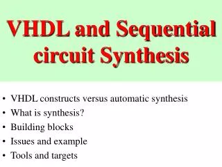
Dsign Automation Automatic transformation of HDL code into a gate level netlist is called “SYNTHESIS” Every vender has its own tools for synthesis, however they all use the flow shown below Specification HDL description Automated Verify Design Target Technology Map design to PLD Download to PLD
PLD Differences... Any Sum of Product (SOP)can be represented by AND-OR. ROM,PAL,PLA are different optimized implementation Of Given Circuit using the AND-OR planes. ROM: AND Fixed, OR Programmable PAL: AND Programmable, OR fixed PLA: AND Programmable, OR Programmable FPGA: Programmable Logic Blocks, Programmable Interconnect
Logic Gates and Programmable switches Outputs (logic functions) Inputs (logic variables) Programmable Logic Device as a black box PLD
PLD x1 x2 xn-1 xn Any combinational logic can be implemented with Sum of Product which is AND-OR implementation. Input buffers And inverters x1 x1 xn xn P1 Pk f1 fm AND Plane OR Plane General Structure of PLD – Programmable Logic Device
Programmable Fuses Connections x1 x2 x3 OR plane P1 P2 P3 P4 SUM f1 f2 AND plane PLA: Gate Level
OR plane x1 x2 x3 P1 P2 P3 P4 AND plane f1 f2 PLA: Customary Schematic
PLA.... • Advantages of PLA • Efficient in terms of area needed for implementation on an IC chip • Often included as part of larger chips such as microprocessors • Programmable AND and OR gates
OR plane (Fixed) x1 x2 x3 P1 f1 P2 P3 f2 P4 AND plane (Programmable)
PAL • PAL - Programmable Array Logic • PLA have higher programmability than PAL, however they have lower speed than PAL Solution PAL for higher speed. • Programmable AND, Fixed OR • PAL - Simpler to manufacture, cheaper than PLA and have better performance
PAL- Extra circuitry.... • Flip-flops store the value produced by the OR gate output at a particular point and can hold it indefinitely. • Flip-flop output is controlled by the clock signal. On 0-1 transition of clock, flip-flop stores the value at its D input and latches the value at Q output. • 2-to-1 multiplexer selects an output from the OR gate output or the flip-flop output. Tri-state buffers are placed between multiplexer and the PAL output. • Multiplexer’s output is fed back to the AND plane in PAL, which allows the multiplexer signal to be used internally in the PAL. This facilitates the implementation of circuits that have multiple stages (levels or logic gates).
Select Enable f1 Flip-flop D Q Clock To AND plane PAL- Extra circuitry: Macrocell For additional flexibility, extra circuitry is added at the output of each OR gate. This is also referred to macrocell.
Example: FSM Implementation S2 = P’ Q y1, R2 = y2, S1 = P’ Q’ , R1 = Q + P Z= y2 y1’ P Q’ , P & Q – are inputs y2 & y1 are the states Z is the output
Programming of PLAs and PALs User circuits are implemented in the programmable devices by configuring or programming these devices. Due to the large number of programmable switches in commercial chips; it is not feasible to specify manually the desired programming state for each switch. CAD systems are used to solve this problem. Computer system that runs the CAD tools is connected to a programming unit. After design of a circuit has been completed, CAD tool generates a file (programming file or fuse map) that specifies the state of each switch in PLD. PLD is then placed into the programming unit and the programming file is transferred from the computer system to the unit. Programming unit then programs each switch individually.
Programming of PLAs and PALs.... PAL (or PLA) as part of a logic circuit resides with other chips on a Printed Circuit Board (PCB). PLD has to be removed from PCB for programming purposes. By placing a socket on PCB makes the removal possible. Plastic leaded chip carrier (PLCC) is the most commonly used package. Instead of using a programming unit, it would be easier if a chip could be programmed on the PCB itself. This type of programming is known as in-system programming (ISP).
SPLD & CPLD... Simple PLDs, Single AND_OR plane It is configured by programming the AND and OR plane, or may be the Flip Flop inclusion and feedback selection, Usually has less than 32 I/O They are available in DIP (Dual in line package), PLCC (Plastic Lead Chip Carrier up to 100 pins. Usually less than 100 equivalent gates. Complex PLDs Multiple AND-OR planes Extend the concept of the simple PLDs further by incorporating architectures that contain several multiple logic block PAL models. Most CPLD use programmable interconnect. Can accommodate from 1000 to 10,000 equivalent gates. Are available in PLCC and QFP (Quad Flap Pack) up to 200 pins
Complex Programmable Logic Devices: CLPD Chips containing PLDs are limited to modest sizes, typically supporting number of input and output more than 32. To accommodate circuits that require more input and outputs, either multiple PLAs or PALs can be used or a more sophisticated type of chip, called a complex programmable logic device (CLPD). CLPD is made up of multiple circuit blocks on a single chip, with internal wiring to connect the circuit blocks. The structure of CLPD is shown on the next slide. It includes four PAL-like blocks connected by interconnection wires. Each block in turn is connected to a sub-circuit I/O block, which is attached to a number of input and output pins.
I/O block I/O block PAL-like block PAL-like block PAL-like block PAL-like block Interconnection Wires I/O block I/O block Complex Programmable Logic Devices: CLPD
PAL-like Block PAL-like Block D Q D Q
Programming of CLPDs CLPD uses quad flat pack (QFP) type of package. QFP package has pins on all four sides and the pins extend outward from the package with a downward-curving shape. Moreover, QFP pins are much thinner and hence, they support a larger number of pins when compared to the PLCC packing. Most CPLDs contain the same type of switch as in PLDs. Here, a separate programming unit is not used due to two main reasons. Firstly, CLPDs contain 200 + pins on the package, and these pins are often fragile and easily bent. Secondly, a socket would be required to hold the chip. Sockets are usually quite expensive and hence, add to the overall cost incurred.
Programming of CLPDs.... CLPD usually support the ISP technique. A small connector is included on the PCB and is connected to a computer system. CLPD is programmed by transferring the programming information from the CAD tool to into the CLPD. The circuitry on the CLPD that allows this type of programming is called JTAG, Joint Test Action Group port, and is standardized by the IEEE. JTAG is a non-volatile type of programming i.e programmed state is retained permanently (for example, in case of power failure, CLPD retains the program).
PLDs & FPGAs The distinction between the two is blurred Although PLDs started as small devices, today’s PLDs are anything but simple. FPGAs fill the gap between PLDs and complex ASICs In both cases, you can program the devices yourself, using design entry and simulation. All FPGAs have regular array of basic cells that are configured by the programmer using special software that program the chips by programming the interconnection. Each vendor has tool supplier that provides custom tools for their products. The programming methodology is usually non permanent, allowing re-programmability
FPGAs & MPGAs Advantage: FPGAs have lower prototyping costs FPGAs have shorter production times Disadvantage: FPGAs Have lower speed of operation in comparison to MPGAs Say by a factor 3 to 5 FPGAs have a lower logic density in comparison to MPGAs Say by a factor of 8 to 12
FPGAs Consists of uncommitted logic arrays and user programmable interconnection. The interconnect programming is done through programmable switches The Logic circuits are implemented by partitioning the logic into blocks and then interconnecting the blocks with the programmable switches The architecture of an FPGA varies from device to device , vendor to vendor it can be based on CPLDs, EPROMS, EEPROMS, LUT, Buses, PALS The interconnect is also varied from EPROM, static RAM, antifuse, EEprom
FPGAs Classifications FPGA types Implementation Architecture Logic Implementation Interconnect Technology Symmetrical Array Row based Array Hierarchial PLD Sea of Gates Look Up table Multiplexer based PLD Block NAND Gates Static Ram Antifuse E/EPROM
FPGA Consists of an array of uncommitted elements that can be interconnected in a general way. Like a PAL the interconnection between the elements are user programmable. The interconnect compromises segments of wires, where segments may be of various lengths. Present in the interconnect are programmable switches that serve to connect the logic blocks to the wire segments or one wire segment to another. Logic circuits are implemented in the FPGA by partitioning the logic into logic blocks and then interconnecting the blocks as required via switches. To facilitate the implementation of a wide variety of circuits, it is important that an FPGA be as versatile as possible. There are many ways to design an FPGA, involving trade offs in the complexity and flexibility of both the logic blocks and the interconnection resources.
FPGA.... Logic Block and Interconnection: The architecture of logic blocks vary from simple combinational logic to complex EPROMs, LUT, Buses etc.. The routing architecture can also be variable including pass-transistors controlled by static RAM cells, anti fuses, EPROM transistors. Each company provides a variety of architecture of the logic blocks and routing architecture.
I/O Cell Logic Block CONCEPTUAL FPGA Interconnect Resources
Classes of common commercial FPGA Symmetrical Array Row-based Interconnect Interconnect Logic Block Logic Block Hierarchical PLD Sea-of-Gates Interconnect overlayed on Logic Blocks PLD Block Interconnect Various Block Architecture & Routing Architecture
Altera 40nm FPGA’ahttp://www.altera.com/literature/br/br-stratix-iv-hardcopy-iv.pdf • Notes: • Y = I/O count, Z = package type (see the product catalog for more information) • ASIC gates calculated as 12 gates per logic element (LE), 5,000 gates per 18 x 18 multiplier(SRAMs, PLLs, test circuitry, I/O registers not included in gate count) • Not including MLABs
Design Entry Logic Optimization Design Flow Process Diagram Technology Mapping Placement Routing Programming Unit Configured FPGA
Implementation Process (overlook) • A designer implementing a circuit on an FPGA must have access to CAD • tools for that type of FPGA. The following steps summarize the process • Logic Entry: Either simulate capture or entering VHDL description or specifying Boolean expansions. • Translate to Boolean & optimize • Transform into a circuit of FPGA logic blocks through a technology mapping program (minimizing # of blocks). • Decides what to place in each block in FPGA array (minimizing total length of interconnect) • Assigns the FPGA’s wire segments and chooses programmable switches to establish required interconnection.
Implementation Process (overlook).... • The output of the CAD system is fed to the programming unit that • configures the final FPGA chip. • Depending upon correct VHDL or design entry, the entire process of • implementing a circuit in an FPGA can take from a few minutes to about and hour.
Shannon's Expansion Theoram Any logic function can expanded in form of a Boolean variable: F= A.F + A.F For example assume F= A.B + A.B.C + A . B. C Then in the expansion F = A [A.B + A.B.C + A. B. C]+ A [ A.B + A.B.C + A. B. C ] = A. [B.C ] + A [ B + C ] Then this can be implemented with a MUX A F1 F2 F1 F2 F
C F2 F 1 B A 0 F1 C B Shannon's Expansion Theoram.... MUX 0 1 F1 = B . C F2 = B + C These functions can be broken down further into: F1 = B ( B . C ) + B ( B . C ) = B . C + B . 0 Control Overall Function 0 F1 C B F2 = B ( B + C ) + B ( B + C ) = B . 1 + B . C C F2 1 B
Shannon's Expansion Theoram Functions can also be expanded into canonical form. Then F is expanded as F= A.B + A.B.C + A . B. C F = A . B ( C + C ) + A . B . C + A . B . C = A . B . C + A . B . C + A . B . C + A . B . C = A . B . C + A ( B . C + B . C + B . C ) = A . F1 +A. F2 In turn this can be implemented in MUX: A F1 F2 F
Shannon's Expansion Theoram.... Therefore 2-1 multiplexer is a general block that can represent any gate: AND Gate F = A . B F = A . ( A . B ) + A ( A . B ) = A . B + A . 0 Ex-OR OR Gate F = A . B + A . B F = A ( A + B ) + A’ ( A + B ) = A + AB + A’. B = A . 1 + A’ . B B B 0 C F F B 1 B A A A
10 ‘1’ ‘1’ Functions that can be implemented using just 2:1 MUX (No inverter at the input). If there are no 2 input rails available, XOR, NAND & NOR cannot be implemented directly. There is a need for more MUXs to be used as inverters.
ACTEL FPGA ACT1 module has three 2:1 Muxs with AND-OR logic at the select of final MUX and implements all 2 input functions, most 3 input and many 4 input functions. Software module generator for ACT1 takes care of all this. Apart from variety of combinational logic functions, the ACT1 module can implement sequential logic cells in a flexible and efficient manner. For example an ACT1 module can be used for a transparent Latch or two modules for a flip flop.
SA S1 A0 A1 Y B0 B1 SB S0 I/O Blocks Logic Module Rows Channel Routing I/O Blocks I/O Blocks I/O Blocks General Architecture of Actel FPGAs ACT-1 Logic Module
Act 1 Programmable Interconnect Architecture The basic Architecture of Actel FPGA is similar to that found in MPGAs, consisting of rows of programming block with horizontal routing channels between the rows. Each routing switch in these FPGAs is implemented by the PLICE Anti fuse. Connections are all and or but shown only in this section for clarity LM LM LM LM LM Wiring Segment Output Track Input Segment Anti fuse Clock Track Vertical Track LM LM LM LM LM
M1 A0 A0 0 1 F 0 1 F A1 F1 A1 SA S F1 M2 SA B0 0 1 B0 B1 F2 F2 S3 S3 SB B1 M2 O1 S0 SB S1 S3 S0 O1 S1 D 0 1 F 0 1 ‘1’ F1 F = A.B + B.C +D = B [A.B + B.C + D] + B[A.B + B.C + D] = A.B + B.D + B.C + B.D = B.(A+D) + B (C+D) C S M2 D 0 1 ‘1’ F2 S3 A O1 ‘0’ B ACTEL Logic Module ACTEL – Implementation using pass transistors M1 ACTEL An example logic macro
M1 M1 D00 D00 SE D01 D01 Y OUT Q Y D10 D10 D11 D11 A1 A1 B1 B1 S1 S1 S0 S0 A0 A0 1 0 B0 CLR CLK S-Module (ACT 2) ACTEL ACT C-Module S-Module (ACT 3) SE (Sequential Element) Slave Latch D00 SE D01 Master Latch Q Y Q D10 1 0 Z D Z D11 C2 SE C1 A1 CLR B1 D Q S1 S0 CLK Combinational Logic for Clear and Clock C2 C1 CLR A0 B0 CLR CLR CLK
ACT1 AND ACT3 LOGIC MODULES ACT1 module is simple logical block. It does not have built in function to generate a Flip Flop. Although it can generate a FF if required. ACT2 and ACT3 that has separate FF module is used for Sequential Circuits. Timing Models & Critical Path Exact timing (delays) on any FPGA chip cannot be estimated until place and routing step has been performed. This is due to the delay of the interconnect. A critical path of SE in is shown on the next slide.
Model with numerical values Taking S-module as one sequential cct View from inside looking out View from outside looking in Actel ACT3 timing model
TABLE 5.2 ACT 3 timing parameters* [1] Fanout Family Delay* 1 2 3 4 8 ACT 3-3 (data book) t PD 2.9 3.2 3.4 3.7 4.8 ACT3-2 (calculated) t PD /0.85 3.41 3.76 4.00 4.35 5.65 ACT3-1 (calculated) t PD /0.75 3.87 4.27 4.53 4.93 6.40 ACT3-Std (calculated) t PD /0.65 4.46 4.92 5.23 5.69 7.38 ACT timing parameters * VDD = 4.75 V, T J ( junction) = 70 °C. Logic module + routing delay. All propagation delays in nanoseconds. * The Actel '1' speed grade is 15 % faster than 'Std'; '2' is 25 % faster than 'Std'; '3' is 35 % faster than 'Std'.
TABLE 5.3 ACT 3 Derating factors* [1] Temperature T J ( junction) / °C V DD / V –55 –40 0 25 70 85 125 4.5 0.72 0.76 0.85 0.90 1.04 1.07 1.17 4.75 0.70 0.73 0.82 0.87 1.00 1.03 1.12 5.00 0.68 0.71 0.79 0.84 0.97 1.00 1.09 5.25 0.66 0.69 0.77 0.82 0.94 0.97 1.06 5.5 0.63 0.66 0.74 0.79 0.90 0.93 1.01 ACT timing parameters.... • Worst-case (Commercial): VDD = 4.75 V, T A (ambient) = +70 °C. Commercial: VDD = 5 V ± 5 %, • T A (ambient) = 0 to +70 °C. Industrial: VDD = 5 V ± 10 %, T A (ambient) = –40 to +85 °C. • Military VDD = 5 V ± 10 %, T C (case) = –55 to +125 °C.
Look Up Table (LUT) A k input LUT can implement any Boolean function of k variables. The inputs are used as addresses that can retrieve the 2k by 1-bit memory that stores the truth table of the Boolean function. Since the size of the memory increases with the number of inputs, k, in order to optimize this mapping and reduce the size of the memory there are a variety of algorithms that map a Boolean network, from a given equation, into a circuit of k-input LUT. These algorithms minimize either the total number of LUTs or the number of levels of LUTs in the final circuit. Minimizing the total number of LUTs reduces the CLB requirements while minimizing the levels of LUTs improves the delay.