Download
1 / 13
130 likes | 228 Vues
Explore the capabilities of Digilent System Board with Serial & Parallel Ports, Pushbutton, LED, and more. See how to leverage these features in designs. Discover the potential of RS232 UART, CPLD interfacing methods, PS2 port, VGA display, and 2-wire serial LCD. Enhance your system projects with these versatile options.

E N D
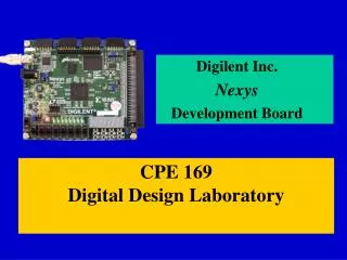
Digilent System Board Capabilities • Serial Port (RS-232) • Parallel Port • 1 Pushbutton • Hint: Good for a reset button • Connected to a clock input. See Digilent Inc.'s reference design for how use it • 1 LED • 50 Mhz Oscillator • GCK0 (pin 80)
RS232 • 5 wire serial interface • Rx,Tx • RTS,CTS (hardware flow control) • DSR • Requires a UART • Rx and Tx are the only lines needed • RS-232 UARTS • Opencores.org (several) • Xilinx appnotes (several) • http://www.xilinx.com/apps/xapps.htm
RS232 UART • Functions • Parallel-serial conversion (transmit) • Serial-parallel conversion (receive) • Start bit, stop bit, parity bit(optional) • Baud rate generation (not always) • UART uses the start bit to syncronize its internal clock to the incoming data • Stop bit indicates end of data • Misread or missing stop bit indicates a framing error • Parity Bit • XOR operation • Detects single bit errors
Parallel Port • 8 bit data transfers • No serial to parallel conversion needed • Extra control lines required • Address Strobe, data strobe, interrupt, reset, write enable • 2 Mbit/s capable • EPP timing diagrams not given in users manual • Specified in IEEE 1284 Standard • http://www.fapo.com/ieee1284.htm • http://www.lvr.com/parport.htm
XC95108 CPLD • Interfaces between Discrete devices and FPGA • 7 segment displays • LED's • Switches • Buttons • Timing Diagrams • Page 15 of dio2 users manual • DIO2 board does not have a local oscillator • 7-segment display uses BOCI input signal • 256Hz – 1kHz input clock required
CPLD Interfacing • LED and 7-segment are write only • Must write to all devices at that address simultaneously • Buttons and switches are read-only
Buttons & Switches • Must poll CPLD to detect when a button or switch has changed • The CPLD does NOT debounce the inputs • 1ms debounce for pushbuttons needed • 2ms debounce for switches needed • The CPLD does NOT sychronize the asynchronous inputs • Inputs will be asynchronous to the FPGA
DIO2 Self test • Starting self Test • SW1 => VDD • SW8 => GND • Press Button 7,E, & 0 to start self-test • Press Button 0 to finish self-test • Self-test • Buttons control LED • Switches control 7-segment displays
PS2 port • Keyboard or Mouse input • Interfacing with Keyboard or Mouse similar to RS-232 protocol • 1 start bit • 1 stop bit • 1 parity bit • Separate clock line used to synchronize data • More reliable than start bit • No baud rate generation required (input clock gives the baud rate) • Half-duplex 2-wire serial
LCD • Samsung KS0066 Controller • 208 preset characters • 8 user defined • 80 character RAM (Frame buffer) • Only 32 can be displayed at any time • Informative LCD site • http://www.hantronix.com/3_3.html • Application notes • Data sheets
VGA • 8 bit color (3 green, 3 blue, 2 red) • 60 Hz, 640 x 480 display • Write every pixel to screen in 16.7 ms • 307,200 pixels on a 640 x 480 display • 2,457,600 bit frame buffer needed (300 Kbytes) • 17.6 Mbytes/sec bandwidth from FPGA to Monitor • Easily done by FPGA • Getting data into FPGA is a problem • 56 Kbits Block RAM available • Could possibly hold a 80 x 80 frame buffer • Use internal FPGA logic for a larger frame buffer