Download
1 / 23
230 likes | 512 Vues
Saga of the IBL Staves . Franck Cadoux on behalf of the ATLAS IBL engineering team (and Eric Vigeolas in particular). Saga of the IBL Staves Topics to be discussed. IBL project & its challenges Stave design and its history… Stave manufacturing & Testing

E N D
Saga of the IBL Staves Franck Cadouxon behalf of the ATLAS IBL engineering team (and Eric Vigeolas in particular)
Saga of the IBL Staves Topics to be discussed IBL project & its challenges Stave design and its history… Stave manufacturing & Testing From a bare object up to integration What we’ve learnt…(still learning!)
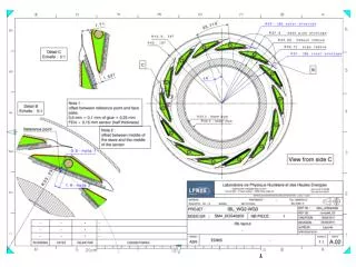
Saga of the IBL Staves IBL project & its challenges Beam pipe Current PIXEL detector IBL location (envelope in blue) PIXEL after de integration @ CERN
Saga of the IBL Staves IBL project & its challenges • IBL project is really short in time (driven by LS1) • Beam pipe is now part of the IBL • Envelopes are tight ( ID=56mm < IBL < OD=85mm…see next!) • Tricky operations in the pit (insertion thru 7m long pipe called IST) • 14 Staves (detectors) cooled @ -40°C with an evaporative CO2 system IST (ID85mm) IPT (ID58mm)
Saga of the IBL Staves IBL project & its challenges • IBL overview • 14 Staves (or Local support) arranged cylindrically around the IPT • (one of the two key structures, or Global supports) • The IST (or IBL Support Tube) is a 6.6m long cylinder tied to the PIXEL • The IPT will position the Staves and support their services IST cutout (to look at the IBL package) IPT with services
Saga of the IBL Staves IBL project & its challenges • IST and IPT manufacturing challenges • IST and IPT manufacturing (both carried out in Seatlle) • Material is a prepreg of K13C (same as for Staves!) • Driven by weight reduction (extremely rigid CFRP… fiber around 900 Gpa) • IST is 0.45mm thick, 6600mm long, 5 segments jointed in a second step • IPT is 0.45mm thick, except in its central area (Staves)… 0.325mm thick!! IST prototype segment IPT proto assembly with rings
Saga of the IBL Staves Stave design and its history • Main design requirements (Stave) • As usual the outstanding features are: Lightweight(X0), Stiffness, Stability • Support 2 types of modules to be cooled down to -40°C all way long (650mm) • Stave fixation to “Global structure” driven by the IBL insertion into the pit! • Radiation hardness for every material (350 MRadat maximum) • Overall Stave planarity should be within +/- 150 µm (see later…) • Cable bus (flex) bonded to Stave due to tight envelopes Stave IPT
Saga of the IBL Staves Stave design and its history • IBL Stave evolution over the last 4 years (coordinated by CPPM Marseille) • Based on the PIXEL experience, several concepts have been studied… • … on CFRP type for omega shape (M60 vs K13C), carbon foam (Pocovs K9), • cooling pipe (CFRP vs Titanium) and the stave shape! • Everything led by the material optimization, reliability… and manufacturing
Saga of the IBL Staves Stave design and its history IBL Stave Design and details… • A bare stave (w/o module) is 748 mm long • 3.5mm thick, and weighs about 26 g • Made of 12 parts glued together • K9 foam choice after LBNL investigations: • Low density (0.22 g/cm3)… but good Thermal conductivity (40 W/m.K) • Stave end parts made of peek CF (inspired by PIXEL staves…) • CFRP Face plate inserted between foam and Module • Prevent TH grease penetration, increase the stiffness, • and allow for HV protection (parylene coating)
Saga of the IBL Staves Stave design and its history Some details on design… Developed by Wuppertal, gluing tests on 2 samples (between Ti pipe and foam)… Clearly shows glue penetration issues This led to some new ideas (face plate in K13C/RS3)… thanks to developments by SLAC + Seattle (avoid the grease underneath module to be soaked up by carbon foam) Short length proto by SLAC (tested @ UniGe) • Layup of K13C facings • (Omega and face plate) • [0°/90°/0°] • Overall thickness: 195µm (quite thin) K9 CNC machined Tomography of K9 K9 plates from Allcomp
Saga of the IBL Staves Stave design and its history Some details on design… Thermal Grease is scraped over the module surface by means of mask and centering tools (see next) Tested without the face plate (grease tends to be soaked up or diffused into the foam pores) Grease being applied onto the Stave face plate + scraping over the mask… All those testes performed on prototypes led to the validation of the STAVE before mass production Result of thermal grease “footprint” when mask is taken out (in this way, the grease amount is well known)
Saga of the IBL Staves Stave manufacturing & Testing • Manufacturing was done in Germany (led by Wuppertal with IVW)… • An initial target of 32 bare Staves + 10 protosto be manufactured • (a bit less to be loaded at the end of the history) • Based on the PIXEL Stave experience (molds, counter molds, CNC machining) • Graphite material used for molds … • …due to high temperature curing (@120°C)… • Co curing was abandoned (material saving OK, but • delimitation still an issue… further developments • needed! • Such a work (12 pieces to be assembled) • is long process and difficult for mass prod. Remachining of foam Tomography of first proto PIXEL shapelegacy Nowit’s a V-shape due to Flex bonding CFRP wrapping @ 12 bars pressure CFRP Omega at 195µm (good homogeneity)
Saga of the IBL Staves Stave manufacturing & Testing • Main steps of the Stave manufacturing…. K13C/RS3 prepregunrolling (for Omega + face plate shaping) End blocks machining (peek CF) K9 foammachining (6 blocks per stave) Staveiscomplete 12 steps are needed to complete 1 bare Stave (post machining required some fine tuning…)
First lessons from the Stave “pre production” step • (improvements on fabrication process) Saga of the IBL Staves Stave manufacturing & Testing Strip on cooling pipes found on 2 staves vacuum bag removal during stave gluing process was suspected First staves prototypes showed cracks on Omega Machining process was changed successfully … no crack observed afterwards …
Saga of the IBL Staves Stave manufacturing & Testing • Thermal qualification (on “Stavelet” + Stave full length proto) • Several dummy staves were tested to select the best design (thermal grease, glue…) • 2 final staves equipped with Si heaters + CO2 cooling • TFOM (Thermal Figure Of Merit) < 15°C.cm2/W • (30°C.cm2/W is the maximum) • 350 thermal cycles [-30°C; +40°C], 50 cycles [-40°C; +50°C], • 10 pressure cycles [1;66 bars] and pressure shock up to • 150 bars! No TFOM change has been seen! Si heaters + thermal sensor (over full length)
Saga of the IBL Staves Stave manufacturing & Testing • Some metrology results… • An extensive campaign of metrology was done to record any change in planarity before and after thermal cycling (with and w/o Flex glued to the Stave) • After Stave Module loading, thermal cycling is performed systematically to select things… so far, the deformations are close to the limits, but still OK! Staves with modules Metrology at UniGe
Saga of the IBL Staves Stave manufacturing & Testing • Some detailed FEA were done to “help” designing the Staves • The policy was to get several lab working on Stave FEA to X-Check results (CPPM, LAPP, CERN, INFN Milano, UniGe) • Both mechanical and Thermo mechanical FEA have been carried out (ANSYS, Abaqus) • Tests on prototypes to get to the “MODEL calibration”… Flex Extensive FEA’s to validate the choice of the Face plate option (1 ply, 3 plies, a few cut out at module location…). For ∆T= -60°C, the ∆Zmax =15 µm… instead of 65 µm w/o face plate! No measurement of TH deflection has been done on proto Flex
Saga of the IBL Staves Stave manufacturing & Testing • Comparison between Test and FEA (mechanics, simply loaded stave) • Stave is held by its handling frame (used from early step to final integration) • A concentrated loading is done at the ¼ of stave length (see below) Stavewith Flex weights Stave onto the handling frame: “final” boundary conditions … Tends to lift up slightly loading Betterthan 15 % difference
The first phase is about “Module Loading” onto the stave… • Aluminum jigs have been designed and successfully tested on the first protos • Every step of the process is safely recorded in a Data Base (useful in case of pb) • Precision is given by the jig thru the Handling frame Saga of the IBL Staves From a bare object to Integration Loadingjig (main tool) Stave on its handling frame
Saga of the IBL Staves From a bare object to Integration • The main steps of the loading process… Nowready for final QA (electrical tests, thermal cycling, metrology…) Repair on module isstilldoable… but risky!
Integration onto the IPT @ CERN (building SR1) • Pretty long object (the cooling line brazing is done before integration)… 7m long! • A dedicated Integration Stand is under fabrication (UniGe is responsible)… • sort of multi purpose object to …Integrate, store, insert thru the IST the IBL package Saga of the IBL Staves From a bare object to Integration Brazing technique undertesting @ CERN + Brazing Stand The Integration stand Multipurpose container (MPC) + Loading stand (central area)
Integration onto the IPT @ CERN (building SR1) • Stave are assembled first, then the services are connected …and tested! • The challenge is to insert a stave with very close neighbors (< 0.9mm clearance… so envelope check will be an issue! Saga of the IBL Staves From a bare object to Integration Loading stand IBL _ MPC (6.6 m long) Envelope checks IPT Loading stand Stave Handling frame IPT
Saga of the IBL Staves What we’ve learnt… • Over the 4 years of manufacturing… • Stave manufacturing is a lengthy operation difficult to “duplicate” among institutes • (tooling, jigs, know how…)… so to be thought about for the next Upgrades! • Material procurement was always tricky (K13C, foam, pipe…)…even if for the layup we took advantage of the IST-IPT business! • So many pieces to glue together… but at the end, the result is pretty satisfactory (planarity, rigidity… and close to FEA predictions!). • Main drawback is about the brittleness of the Omega + Face plate (due to very high modulus fibers)… special care applied to the post machining • Towards the next years… • Still some challenges to be faced on Stave Integration (envelope issues) • About K13C layup…is it really needed ?? Seems to be “too much”… • Think about even thinner cooling pipe, and smaller diameters?? To save further material… • Try to optimize the amount of glue… especially at cooling line joint • … but the feeling that we are close to some current limits / mechanics…(material, glues, ?) • Optimize the links (number of fixations) to the Global structures (like IST) is challenging