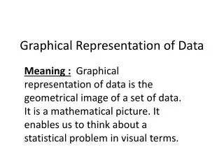
A Graphical Representation of COTS-based Software Architectures
200 likes | 464 Vues
A Graphical Representation of COTS-based Software Architectures. Raúl Monge – UTFSM, Valparaiso, Chile Carina Alves – University College, UK Antonio Vallecillo – Universidad de Málaga , Spain (Supported by “ WEST ” project). Intro/Motivation.

A Graphical Representation of COTS-based Software Architectures
E N D
Presentation Transcript
A Graphical Representation of COTS-based Software Architectures Raúl Monge – UTFSM, Valparaiso, Chile Carina Alves – University College, UK Antonio Vallecillo – Universidad de Málaga, Spain (Supported by “WEST” project)
Intro/Motivation • Complex software systems require expressive notations for describing and analysing their “software architectures” • ADLs are OK, but unfriendly • UML is friendly, but not completely fit • ...and then?
Goal of our work • Propose a graphical notation for representing software architectures • Using UML • Only for COTS-based systems • Not only for describing structures... • ...but also with quality-related “properties” • Future extensions for dealing with NFRs
Agenda • Background • Software Architectures, ADLs, UML • Our proposal • Description • An example • Conclusions • Discussion • Future work
Software Architecture • Defines the high-level structure of a system, in terms of a collection of interacting components and the relationships among them • Concepts/Elements: • Components (computational elements & data stores) • Ports (“typed” points of interaction) • Connectors (interactions among components) • Roles (“typed” roles that participants play) • Systems (collections of components & connectors) • Properties (extra-functional and quality aspects) • Styles (represent families of related systems)
ADLs • Architectural Description Languages • Usually allow • The [formal] description of the structure and behavior of the software architecture • Some kind of [formal] analysis (safety & liveneness properties, composibility,...) • Examples: Wright, Darwin, C2, Rapide, ... • Usually unfriendly or non-standard graphical notations • Do not account for quality aspects or NFRs
UML for Software Architecture • UML (1.x) does not offer a clear way for encoding and modeling SAs: • Semantic clashes between UML and SA concepts (eg. component, system,...) • No clear mappings between UML and SA concepts (eg. component,...) • Vague semantics of UML vs precise ADL semantics • Semantic gaps for modeling SA concepts (eg. connector, style,...) • OMG has included a request for modeling SA in the UML 2.0 Superstructre RFP
Our proposal • Propose a graphical notation for representing software architectures • Using UML • Only for COTS-based systems • Not only for describing structures... • ...but also with quality-related “properties” • Future extensions for dealing with NFRs
Elements of our proposal • Structural elements • Components and ports • Connectors and roles • Systems • Styles • Properties • Behavioral elements • Behavior • Choreographies • Quality attributes
ports Components
Roles Connectors
Systems, Properties, Styles • Systems • modeled as UML subsystems • Properties • modeled by stereotyped notes • Styles • Expressed in OCL
Qualifying elements • Architectural elements (components, ports, connectors, roles, systems) can be qualified
Conclusions • Simple and easy-to-use notation • Enables different kind of analyses • Allows strutural and behavioral descriptions
Conclusions/Future work • Test and validate with real examples • Tool support for the analyses • Desribe NFRs and the “rationale” behind the architectural decisions • Simple and easy-to-use notation • Enables different kind of analyses • Allows strutural and behavioral descriptions
End of presentation http://www.lcc.uma.es/~av/Publicaciones/02/ideas-76.pps