Electromagnetism
Electromagnetism. BADI Year 2 John Errington MSc. Coils, Motors, Generators and Transformers. History of developments in electromagnetism. 1800: Volta develops the voltaic pile – the first electrochemical cell and battery capable of producing continuous electric current.

Electromagnetism
E N D
Presentation Transcript
Electromagnetism BADI Year 2 John Errington MSc
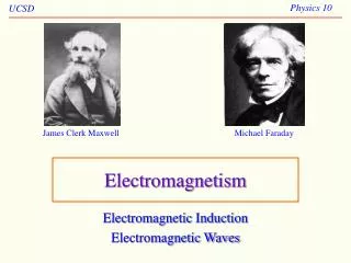
History of developments in electromagnetism • 1800: Volta develops the voltaic pile – the first electrochemical cell and battery capable of producing continuous electric current. • 1820: Oersted discovers a current flowing in a conductor causes a magnetic field. • 1820: Ampere discovers a force between two wires carrying currents. • 1831: Faraday showed electricity could be produced by magnetism. Sets basis for electric motor and generator. • 1860 James Clerk Maxwell produces a set of equations that puts the theory of electromagnetism on a mathematical basis.
Michael Faraday • The Prime Minister of the day is said to have asked him (Faraday) what use could be made of his discoveries. Faraday allegedly responded, "Someday it might be possible to tax them."
Michael Faraday • Faraday's first law of electromagnetic induction • An electromotive force (voltage) is induced in a conductor when the magnetic field surrounding it changes. • Faraday's second law of electromagnetic induction • The magnitude of the electromotive force is proportional to the rate of change of the field. • Faraday's third law of electromagnetic induction • The sense of the induced electromotive force depends on the direction of the rate of the change of the field.
Maxwell • The first equation is really Faraday's Law of Induction. It states that an induced electric field (E) is created by a changing magnetic flux density (dB/dt) with a polarity that opposes the changing magnetic field (-). The faster the flux density changes, the greater the induced electric field. • In the second equation, Oersted and Ampere and Gauss showed that a current (J) would create a magnetic field (H). However, Maxwell took it further and showed that a magnetic field (H) is created by a current (J) and a changing electric field (dD/dt). • In the third equation, Coulomb and Gauss showed that an enclosed electrical charge (p) will create a net electric field (D). In other words, if you were to enclose an electron within a soap bubble, there would be a net electric field created by that electron which is a single negatively charged particle. • The fourth equation, also by Gauss, states that an enclosed magnet will have a net magnetic flux (B) of zero. In other words, every magnet has a north pole and a south pole, so that if you were to enclose even a part of a magnet within a soap bubble, the total number of magnetic field lines entering the bubble would equal the total number of magnetic field lines exiting the bubble, with a net of zero. Thus there is no monopole, or particle, which has just one magnetic pole without the other. This would be like having a magnet with just a north pole, but no south pole.
Conductors carrying current generate a magnetic field. A straight wire carrying a current generates a magnetic field around the wire. The direction of the magnetic field obeys the ‘corkscrew rule’ Current flow
Electromagnets If wire is wrapped around a plastic former to form a coil it will generate a magnetic field when a current is passed through it. The magnetic field strength is proportional to the number of turns, and the current. If you grasp the coil with your right hand with your fingers pointed in the direction of current flow your thumb will point toward the N pole of the coil.
Magnetic field around a single loop Magnetic field in an air cored coil Magnetic field in a coil with an iron core The size of the air gap has the biggest influence on the strength of the magnet
+ S - Basic circuit Coil of wire Switch Battery Car sidelight bulb limits current 12V 5W
Inductance of coil The inductance of an electromagnet is L (in Henrys) = n2 a / l where: n = no of turns = absolute permeability of core a = area of coil in sq metres l = length of coil in metres The absolute permeability of air 0 is 4 X 10⁷ Relative permeability rranges from 1 for air, wood, aluminium & plastics to 3000 for soft iron, silicon steel and ferrites. Absolute permeability is just 0 * r
Permeability • Permeability is a magnetic property of a material, and is often expressed as 0 x r , where • 0 is a physical constant equal to exactly 4*pi*10-7 Henries / meter and • r is the relative permeability. r is equal to 1.0 for free space. • Relative permeability r refers to a material's ability to attract and conduct magnetic lines of flux. The more conductive a material is to magnetic fields, the higher its permeability. • Most materials, including copper aluminium and gold have r near 1.0. The metals that are notable exceptions are nickel, cobalt, manganese, chromium and iron. These are called ferro-magnetic materials, and can have permeabilities as high as 100 or more.
The strength of the magnetic field can be increased by putting an iron rod inside the coil. The shorter you make the air path the stronger the field will be. (This is why horseshoe, button and pot magnets are more popular than bar magnets.) The permeability of iron is about 2000 times higher than that for air, so the more iron and the less air there is in the path the better.
Horseshoe electromagnet • To keep the air gaps small the coils can be wound directly onto iron rods. (e.g. nails or bolts) (It’s best to put a layer of paper first to protect the insulation) Short air path for field
Relay, contactor, or buzzer The electromagnet can be used to operate a switch with one or more sets of contacts – this is called a relay Contacts normally open normally closed Armature Pivot and common contact
+ - Vibration annunciator Here the iron slug slides freely inside the coil. When a current flows through the coil it pulls the slug into the coil. The contact is broken, and the current stops. The spring pulls the slug out again and the process repeats. The frequency of vibration is determined mainly by the strength of the spring and mass of the slug. Coil of wire Iron slug Spring Battery Sliding contact 12V 5W Car sidelight bulb limits current
DC Machines (Motors & Generators) • Permanent magnet • Series coil • Shunt coil DC motors have the same construction as DC generators. Apply a current and the shaft will rotate; rotate the shaft and you will generate a current.
Generator DC split ring commutator brush field V The coil (which may be many turns) is usually wound onto a soft iron core time
Generators DC (other types) Series Shunt Compound N N N A A A S S S + - - + + - i ñ V ò i ñ or i ò V is const
AC Generator (Alternator) Electro magnet commutators N wire coils S brush AC output
Transformer A device for changing AC voltages Vout = Vin * Ns / Np Vin Vout primary secondary Np =6 Ns =12 soft iron laminated core
Transformers • Can step ac voltages up and down • Provide electrical isolation between circuits to protect patient safety etc. • Don’t work with dc
Transformer example A mains transformer provides 12 V ac for a 48W halogen light. The voltage ratio needed is 240 V / 12 V so the turns ratio needed is 20 (primary) : 1 (secondary) In practice the transformer would have many more turns than this to provide the right ratio. Note that as the voltage is stepped down (240 V : 12V) so the current is stepped up (0.2A to 4 A) L 48W = 240V * 0.2A 48W = 12V * 4A N Iron cored transformer
Resources • www.gcsescience.com basic electromagnetism etc. • www.magnetsinfo.com/ bumf about metal and ceramic magnets • www.4qd.co.uk/ a thorough introduction to motors of all types • www.psigate.ac.uk Physics gateway • scienceworld.wolfram.com