CONTAINMENT SPRAY
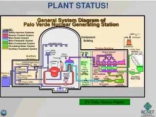
PLANT STATUS!. General System Diagram of. Palo Verde Nuclear Generating Station. Legend::. Safety Injection Systems. Reactor Coolant System. To Switchyard. Containment Building. Main Steam System. Main Feedwater System. Main Condensate System. CONTAINMENT SPRAY.

CONTAINMENT SPRAY
E N D
Presentation Transcript
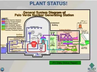
PLANT STATUS! General System Diagram of Palo Verde Nuclear Generating Station Legend:: Safety Injection Systems Reactor Coolant System To Switchyard Containment Building Main Steam System Main Feedwater System Main Condensate System CONTAINMENT SPRAY Circulating Water System Transformer Turbine Building Auxiliary Feedwater System Cooling Tower and Fans Safety Injection Tank Moisture Separator Reheaters MSSVs ADVs 8 8 8 Steam Generator Auxiliary Building MSIV Pressurizer MTSV Control Rods MSSS Shutdown Heat Exchanger HP LP LP LP Generator Bldg. Turbine Turbine Turbine Turbine Equipment Cooling MTCV Z From Auxiliary Feedwater Pumps Containment Spray Pump Turbine Bypass Valves Reactor Core Refueling Water Tank Condensate Pump Reactor Coolant Pump Main Condenser Low Pressure Safety Injection Pump (HP) Feedwater Heaters (LP) Feedwater Heaters Circulating Water Pump High Pressure Safety Injection Pump Feedwater Regulation Valve Main Feedwater Pump Polishing Demineralizers Containment Sump PV Daily Status Report
IT’S OUR RESPONSIBILITY! NUCLEAR SAFETY INDUSTRIAL SAFETY RADIOLOGICAL SAFETY SAFETY CULTURE
BALANCE OF PLANT ENGINEERED SAFETY FEATURE ACTUATION SYSTEM COURSE/LESSON TERMINAL OBJECTIVE: GIVEN THE APPLICABLE REFERENCE MATERIALS, THE I&C TECHNICIAN WILL DESCRIBE THE DESIGN, OPERATION AND MAINTENANCE ON THE BALANCE OF PLANT ENGINEERED SAFETY FEATURES ACTUATION SYSTEM. PROFICIENCY WILL BE DEMONSTRATED BY ACHIEVEMENT OF AT LEAST 80% ON A WRITTEN EXAMINATION
Which of the following is not an actuation signal from BOP-ESFAS • FBEVAS • CPIAS • SIAS • CRVIAS
Which BOP-ESFAS function is manual initiation only? • CPIAS • CRVIAS • DGSS • LOP/LS
FBEVAS channel “A” is in bypass. Manual initiation at B05 will not cause a FBEVAS. • True • False
All BOP-ESFAS relays are normally energized and will de-energize to actuate loads. • True • False
Placing both A & B trains of CPIAS in bypass will cause: • Both trains to be bypassed • CPIAS to be initiated • Both trains to drop out of bypass • “A” train only to be in bypass
BALANCE OF PLANT ENGINEERED SAFETY FEATURE ACTUATION SYSTEM ENABLING OBJECTIVES: EO01 STATE THE PURPOSE OF THE BALANCE OF PLANT ENGINEERED SAFETY FEATURES ACTUATION SYSTEM. EO02 DESCRIBE THE FUNCTIONS PERFORMED BY THE BALANCE OF PLANT ENGINEERED SAFETY FEATURES ACTUATION SYSTEM.
Purpose • Provides continuous monitoring of selected plant variables • Actuates BOP ESF equipment when monitored parameters exceed setpoints • Provides load sequencing necessary for proper ESF system operation VTM page 2-1
BALANCE OF PLANT ENGINEERED SAFETY FEATURE ACTUATION SYSTEM Minimizes the consequences of the following design base accidents: • Fuel Handling • Fire/Smoke (manual actuation only) • Loss of Power
BIG PICTURE Overview OUTPUTS? INPUTS? BOP ESFAS CREFAS FBEVAS Rad Monitors CPIAS Voltage Monitors CRVIAS PPS ESFAS Loss of Power Manual Load Shed ESF Load Sequencer Equip Start Diesel Start 120 Vac (PN) 125 Vdc (PK)
BALANCE OF PLANT ENGINEERED SAFETY FEATURE ACTUATION SYSTEM EO03 DESCRIBE THE BALANCE OF PLANT ENGINEERED SAFETY FEATURES ACTUATION SYSTEM TO INCLUDE MAJOR COMPONENTS, LOCATION OF PRINCIPAL UNIT AND SOURCES OF POWER. EO04 IDENTIFY THE LOCATION, CONTROLS, INPUTS, AND OUTPUTS OF THE BOP ESFAS CHANNEL POWER SUPPLY.
The Cabinets • Each cabinet receives power from… • Power is distributed… How are the cabinets cooled? 120 Vac 125 Vdc Cooling Fan Cooling Fan AC/DC Converter DC/DC Converter 28 VDC Bus
Each Power Supply is equipped with internal fans Rejects or further suppresses transient line voltages SAFETY FEATURES OVER VOLTAGE OVER CURRENT HIGH TEMPERATURE 120 VAC Vital Power (PNA-D25/PNB-D26) 28 VDC LOW PASS FILTER-rejects high freq noise and transients Monitors P/S temperature and output 125 VDC Vital Power (PKA-D21/PKB-D22) AUCTIONEERING DIODES Remote Light Remote Light and alarm Remote Light 27.75 VDC
BALANCE OF PLANT ENGINEERED SAFETY FEATURE ACTUATION SYSTEM EO05 DESCRIBE THE OPERATION OF THE CONTROLS LOCATED ON THE KEY LOCK SWITCH PANEL. EO06 IDENTIFY THE LOCATION AND FUNCTION OF THE ISOLATOR ASSEMBLY. EO07 STATE THE FUNCTION AND DESCRIBE THE CONSTRUCTION AND OPERATION OF THE FBEVAS MODULE, TO INCLUDE INPUTS, OUTPUTS, TEST FEATURES, CONTROLS, AND INDICATIONS.
Keylock Switch Panel • Located in the A4 assembly of each cabinet. • Keylock bypass switches provided for all module • inputs EXCEPT DGSS and Load Sequencer. • Bypasses are interlocked so same parameter • cannot be bypassed in both trains at the same • time.
8 8
Isolator Assembly • Located in the A5 assembly • 18 optical isolators on a single board • Photodiode optically coupled to a phototransistor • Isolate communication between logic trains “A” and “B” Page 9 of printbook
Example: Page 10 of printbook VTD-G063-00002
BOP ESFAS provides initiating signals to components requiring automatic actuation whenever monitored variables reach levels that require protective action. The actuations that originate from the BOP ESFAS include the following: • Fuel Building Essential Ventilation Actuation Signal (FBEVAS) • Containment Purge Isolation Actuation Signal (CPIAS) • Control Room Ventilation Isolation Actuation Signal (CRVIAS) • Control Room Essential Filtration Actuation Signal (CREFAS). • Loss of Power/Load Shed (LOP/LS) • Diesel Generator Start Signal (DGSS) • Sequencer Output Signals
Safety System Functions • Fuel Building Essential Ventilation Actuation Signal (FBEVAS): • FBEVAS operates two redundant filter trains whenever 1 of 2 high radiation signals are received and maintains negative pressure in the Fuel Building to prevent leakage of unfiltered air to the environment in the event of a fuel handling accident
These actions cause the Fuel Bldg Essential AFUs to start and take a suction of the Fuel Bldg. What if a SIAS and a FBEVAS occur concurrently? Norm Supply… Norm Supply and Exhaust Fans STOP …and Exhaust dampers CLOSE • Essential Exhaust Dampers OPEN • and Essential AFUs START
Signal enters BOP ESFAS Signal passes first “OR” gate. Signal passes second “OR” gate. Signal is then applied to the “AND” gate. RU-31 HIGH What does this do?
RU-31 CLEARS What happens to the signal? How do I clear it?
This goes away as soon as I release the pushbutton How do I clear this signal? I still need to reset at the cabinet
This “AND” Gate blocks the signal from passing Now RU-31 alarms Let’s take a look at the BYPASS.
Here is a scenario… I&C is testing RU-31 with the channel in bypass. Operations then bypasses RU-145. WHAT HAPPENS?
What happens when I take the Channel “A” switch to actuate? I now release the switch. Signal is sealed in, just like before. I need to break the seal in to clear. Pushbutton on BOP ESFAS Cabinet is used. Let’s look at the B05 Controls.
TRIP RESET ACTUATE MAN RST TEST BYPASS
BALANCE OF PLANT ENGINEERED SAFETY FEATURE ACTUATION SYSTEM EO08 STATE THE FUNCTION AND DESCRIBE THE CONSTRUCTION AND OPERATION OF THE CPIAS MODULE, TO INCLUDE INPUTS, OUTPUTS, TEST FEATURES, CONTROLS, AND INDICATIONS. EO09 STATE THE FUNCTION AND DESCRIBE THE CONSTRUCTION AND OPERATION OF THE CREFAS MODULE, TO INCLUDE INPUTS, OUTPUTS, TEST FEATURES, CONTROLS, AND INDICATIONS.
BOP ESFAS provides initiating signals to components requiring automatic actuation whenever monitored variables reach levels that require protective action. The actuations that originate from the BOP ESFAS include the following: • Fuel Building Essential Ventilation Actuation Signal (FBEVAS) • Containment Purge Isolation Actuation Signal (CPIAS) • Control Room Ventilation Isolation Actuation Signal (CRVIAS) • Control Room Essential Filtration Actuation Signal (CREFAS). • Loss of Power/Load Shed (LOP/LS) • Diesel Generator Start Signal (DGSS) • Sequencer Output Signals
Safety System Functions • Containment Purge Isolation Actuation Signal (CPIAS): • CPIAS stops either a Power Access or Refueling Purge by closing inlets and outlets in the event of 1 of 2 high radiation signals. It thus minimizes offsite dose in event of a fuel handling accident in containment
Refuel Purge Upstream UV-2A/2B CLOSE Refuel Purge Downstream UV-3A/3B CLOSE Access Purge Upstream UV-4A/4B CLOSE Access Purge Downstream UV-5A/5B CLOSE The Purge Supply and Exhaust Fans are interlocked with their respective containment isolation dampers causing these fans to trip when the dampers isolate. These actions will also occur upon a CIAS.
Tech Spec 3.3.8 CPIAS • One CPIAS shall be operable • During modes 1-4, core alts or fuel movement in containment • If not, shut down and close containment purge • Minimizes offsite dose in event of a fuel handling accident in containment
BOP ESFAS provides initiating signals to components requiring automatic actuation whenever monitored variables reach levels that require protective action. The actuations that originate from the BOP ESFAS include the following: • Fuel Building Essential Ventilation Actuation Signal (FBEVAS) • Containment Purge Isolation Actuation Signal (CPIAS) • Control Room Ventilation Isolation Actuation Signal (CRVIAS) • Control Room Essential Filtration Actuation Signal (CREFAS). • Loss of Power/Load Shed (LOP/LS) • Diesel Generator Start Signal (DGSS) • Sequencer Output Signals
Safety System Functions • Control Room Essential Filtration Actuation Signal (CREFAS): • Actuated by 1 of 2 Control Room air intake high airborne activity signals, FBEVAS, or CPIAS. It thus minimizes dose to Control Room operators by isolating the normal ventilation and activating the charcoal filter system
HJA-M58 HJB-M10 HJA-M59 HJB-M13 HJA-M02 HJB-M02 HJA-M03 HJB-M03 HJA-M52 HJB-M55 HJA-M01 HJB-M01