FIRES EXPLOSIONS
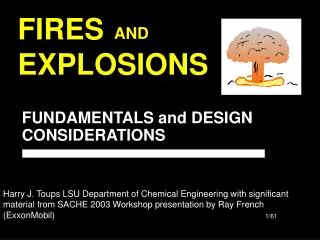
FIRES EXPLOSIONS. AND. FUNDAMENTALS and DESIGN CONSIDERATIONS. Harry J. Toups LSU Department of Chemical Engineering with significant material from SACHE 2003 Workshop presentation by Ray French (ExxonMobil). Fuels: Liquids gasoline, acetone, ether, pentane Solids

FIRES EXPLOSIONS
E N D
Presentation Transcript
FIRESEXPLOSIONS AND FUNDAMENTALS and DESIGN CONSIDERATIONS Harry J. Toups LSU Department of Chemical Engineering with significant material from SACHE 2003 Workshop presentation by Ray French (ExxonMobil)
Fuels: Liquids gasoline, acetone, ether, pentane Solids plastics, wood dust, fibers, metal particles Gases acetylene, propane, carbon monoxide, hydrogen Oxidizers Liquids Gases Oxygen, fluorine, chlorine hydrogen peroxide, nitric acid, perchloric acid Solids Metal peroxides, ammonium nitrate FUEL AIR (OXYGEN) IGNITION SOURCE The Fire Triangle • Ignition sources • Sparks, flames, static electricity, heat
Liquid Fuels – Definitions • Flash Point • Lowest temperature at which a flammable liquid gives off enough vapor to form an ignitable mixture with air • Flammable Liquids (NFPA) • Liquids with a flash point < 100°F • Combustible Liquids (NFPA) • Liquids with a flash point ³100°F
SAME SAME Vapor Mixtures – Definitions • Flammable / Explosive Limits • Range of composition of material in air which will burn • UFL – Upper Flammable Limit • LFL – Lower Flammable Limit • HEL – Higher Explosive Limit • LEL – Lower Explosive Limit • Measuring These Limits for Vapor-Air Mixtures • Known concentrations are placed in a closed vessel apparatus and then ignition is attempted
UPPER LIMIT AUTO IGNITION FLAMMABLE REGION FLAMMABLE REGION VAPOR PRESSURE MIST CONCENTRATION OF FUEL LOWER LIMIT AIT TEMPERATURE FLASH POINT Flammability Relationships
Flash Point From Vapor Pressure • Most materials start to burn at 50% stoichiometric • For heptane: • C7H16 + 11 O2 = 7 CO2 + 8 H2O • Air = 11/ 0.21 = 52.38 moles air /mole of C7H16 at stoichiometric conditions • At 50% stoichiometric, C7H16 vol. % @ 0.9% • Experimental is 1.1% • For 1 vol. %, vapor pressure is 1 kPa temperature = 23o F • Experimental flash point temperature = 25o F
Limiting O2 Concentration: Vol. % O2 below which combustion can’t occur LOC FLAMMABLEMIXTURES HEL LEL Flammability Diagram 1 Atmosphere 25°C
Limiting O2 Concentration: Vol. % O2 below which combustion can’t occur LOC HEL LEL Flammability Diagram 1 Atmosphere 25°C FLAMMABLEMIXTURES
Inerts Temperature Pressure Flammable Limits Change With:
Effect of Temperature onLower Limits of Flammability L E L, %
HEL LEL Effect of Pressure of Flammability Natural Gas In Air at 28oC Natural Gas, volume% Initial Pressure, Atm.
Minimum Ignition Energy • Lowest amount of energy required for ignition • Major variable • Dependent on: • Temperature • % of combustible in combustant • Type of compound
Minimum Ignition Energy Effects of Stoichiometry
Autoignition Temperature • Temperature at which the vapor ignites spontaneously from the energy of the environment • Function of: • Concentration of the vapor • Material in contact • Size of the containment
AUTO IGNITION FLAMMABLE REGION AIT FLASH POINT Flammability Relationships UPPER LIMIT FLAMMABLE REGION VAPOR PRESSURE MIST CONCENTRATION OF FUEL LOWER LIMIT AIT TEMPERATURE
Auto-Oxidation • The process of slow oxidation with accompanying evolution of heat, sometimes leading to autoignition if the energy is not removed from the system • Liquids with relatively low volatility are particularly susceptible to this problem • Liquids with high volatility are less susceptible to autoignition because they self-cool as a result of evaporation • Known as spontaneous combustion when a fire results; e.g., oily rags in warm rooms; land fill fires
Adiabatic Compression • Fuel and air will ignite if the vapors are compressed to an adiabatic temperature that exceeds the autoignition temperature • Adiabatic Compression Ignition (ACI) • Diesel engines operate on this principle; pre-ignition knocking in gasoline engines • E.g., flammable vapors sucked into compressors; aluminum portable oxygen system fires
More Definitions • Fire • A slow form of deflagration • Deflagration • Propagating reactions in which the energy transfer from the reaction zone to the unreacted zone is accomplished thru ordinary transport processes such as heat and mass transfer. • Detonation / Explosion • Propagating reactions in which energy is transferred from the reaction zone to the unreacted zone on a reactive shock wave. The velocity of the shock wave always exceeds sonic velocity in the reactant.
Rapid Equilibration of High Pressure Gas via Shock Wave EXPLOSION = Physical Explosions Chemical Explosions Uniform Reactions Propagating Reactions Deflagrations(Normal Transport) Thermal Explosions Detonations(Shock Wave) Classification of Explosions
Potential Energy Stored Volumes of Ideal Gas at 20° C PRESSURE, psig TNT EQUIV., lbs. per ft3 10 100 1000 10000 0.001 0.02 1.42 6.53 TNT equivalent = 5 x 10⁵ calories/lbm
Deflagration • Combustion with flame speeds at non-turbulent velocities of 0.5 - 1 m/sec. • Pressures rise by heat balance in fixed volume with pressure ratio of about 10. CH4 + 2 O2 = CO2 + 2 H2O + 21000 BTU/lb Initial Mols = 1 + 2/.21 = 10.52 Final Mols = 1 + 2 + 2(0.79/0.21) = 10.52 Initial Temp = 298oK Final Temp = 2500oK Pressure Ratio = 9.7 Initial Pressure = 1 bar (abs) Final Pressure = 9.7 bar (abs)
Detonation • Highly turbulent combustion • Very high flame speeds • Extremely high pressures >>10 bars
Pressure vs Time Characteristics DETONATION VAPOR CLOUD DEFLAGRATION OVERPRESSURE TIME
Two Special Cases • Vapor Cloud Explosion • Boiling Liquid /Expanding Vapor Explosion
U N C O N F I N E D V C E A P O R X P L O S I O N S L O U D • An overpressure caused when a gas cloud detonates or deflagrates in open air rather than simply burns.
What Happens to a Vapor Cloud? • Cloud will spread from too rich, through flammable range to too lean. • Edges start to burn through deflagration (steady state combustion). • Cloud will disperse through natural convection. • Flame velocity will increase with containment and turbulence. • If velocity is high enough cloud will detonate. • If cloud is small enough with little confinement it cannot explode.
Confinement Prevents escape, increases turbulence Cloud composition Unsaturated molecules – ‘all ethylene clouds explode’; low ignition energies; high flame speeds Good weather Stable atmospheres, low wind speeds Large Vapor Clouds Higher probability of finding ignition source; more likely to generate overpressure Source Flashing liquids; high pressures; large, low or downward facing leaks What Favors Hi Overpressures?
Impact of VCEs on People PeakOverpressure psi EquivalentWind Velocity mph Effects 70 160 290 470 670 940 Knock personnel down Rupture eardrums Damage lungs Threshold fatalities 50% fatalities 99% fatalities 1 2 5 10 15 20 30 35 50 65
Impact of VCEs on Facilities PeakOverpressure psi Typical Damage Glass windows break Common siding types fail: - corrugated asbestos shatters - corrugated steel panel joints fail - wood siding blows in Unreinforced concrete, cinder block walls fail Self-framed steel panel buildings collapse Oil storage tanks rupture Utility poles snap Loaded rail cars overturn Unreinforced brick walls fail 0.5-to-1 1-to-2 2-to-3 3-to-4 5 7 7-8
Vapor Clouds and TNT • World of explosives is dominated by TNT impact which is understood. • Vapor clouds, by analysis of incidents, seem to respond like TNT if we can determine the equivalent TNT. • 1 pound of TNT has a LHV of 1890 BTU/lb. • 1 pound of hydrocarbon has a LHV of about 19000 BTU/lb. • A vapor cloud with a 10% efficiency will respond like a similar weight of TNT.
Multi-Energy Models • Experts plotted efficiency against vapor cloud size and … reached no effective conclusions. Efficiencies were between 0.1% and 50% • Recent developments in science suggest too many unknowns for simple TNT model. • Key variables to overpressure effect are: • Quantity of combustant in explosion • Congestion/confinement for escape of combustion products • Number of serial explosions • Multi-energy model is consistent with models and pilot explosions.
B L E V E O I L I N G I Q U I D X P A N D I N G A P O R X P L O S I O N S • The result of a vessel failure in a fire and release of a pressurized liquid rapidly into the fire • A pressure wave, a fire ball, vessel fragments and burning liquid droplets are usually the result
BLEVE FUEL SOURCE
Distance Comparison INVENTORY (tons) UVCE BLEVE FIRE Distancein Meters 1 2 5 10 20 50 100 200 500 1000 120 150 200 250 310 420 530 670 900 1150 18 36 60 90 130 200 280 400 600 820 20 30 36 50 60 100 130
Typical Control Spacing and Layout Spacing and Layout Work Procedures Work Procedures Sewer Design, Diking, Weed Control, Housekeeping Procedures Fire or Flames Furnaces and Boilers Flares Welding Sparks from Tools Spread from Other Areas jkdj dkdjfdk dkdfjdkkd jkfdkd fkd fjkd fjdkkf djkfdkf jkdkf dkf Matches and Lighters Eliminate Ignition Sources
Hot Surfaces Hot Pipes and Equipment Automotive Equipment • Electrical • Sparks from Switches • Static Sparks jkfdkd fjkdjd kdjfdkd • Lightning • Handheld Electrical Equipment Eliminate Ignition Sources • Typical Control • Spacing • Procedures • Typical Control • Area Classification • Grounding, Inerting, Relaxation • Geometry, Snuffing • Procedures
Inerting – Vacuum Purging • Most common procedure for inerting reactors • Steps • Draw a vacuum • Relieve the vacuum with an inert gas • Repeat Steps 1 and 2 until the desired oxidant level is reached • Oxidant Concentration after j cycles: where PL is vacuum level PH is inert pressure
Inerting – Pressure Purging • Most common procedure for inerting reactors • Steps • Add inert gas under pressure • Vent down to atmospheric pressure • Repeat Steps 1 and 2 until the desired oxidant level is reached • Oxidant Concentration after j cycles: where nL is atmospheric moles nH is pressure moles
Vacuum? Pressure? Which? • Pressure purging is faster because pressure differentials are greater (+PP) • Vacuum purging uses less inert gas than pressure purging (+VP) • Combining the two gains benefits of both especially if the initial cycle is a vacuum cycle (+ VP&PP)
Other Methods of Inerting • Sweep-Through Purging • ‘In one end, and out the other’ • For equipment not rated for pressure, vacuum • Requires large quantities of inert gas • Siphon Purging • Fill vessel with a compatible liquid • Use Sweep-Through on small vapor space • Add inert purge gas as vessel is drained • Very efficient for large storage vessels