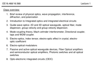
Class overview:
Explore physical optics, wave propagation, interference, diffraction, polarization, integrated optics, and electrical circuits. Study waveguides, modulators, interferometers, and opto-electronic circuits. Gain insights into complex numbers, phases, phase delays, refractive indices, and optical wavefronts. Enhance your knowledge of optical components, interferometric setups, electro-optic effects, and optical fiber applications.

Class overview:
E N D
Presentation Transcript
Class overview: • Brief review of physical optics, wave propagation, interference, diffraction, and polarization • Introduction to Integrated optics and integrated electrical circuits • Guide-wave optics: 2D and 3D optical waveguide, optical fiber, modedispersion, group velocity and group velocity dispersion. 4. Mode-coupling theory, Mach-zehnder interferometer, Directional coupler, taps and WDM coupler. 5. Electro-optics, index tensor, electro-optic effect in crystal, electro-optic coefficient 6. Electro-optical modulators 7. Passive and active optical waveguide devices, Fiber Optical amplifiers and semiconductor optical amplifiers, Photonic switches and all optical switches 8. Opto-electronic integrated circuits (OEIC)
Complex numbers or C: amplitude : angle b C a Real numbers do not have phases Complex numbers have phases is the phase of the complex number
Physical meaning of multiplication of two complex numbers Number: times Phase: Phase delay Why 90 i 180 0 -1 1 -i 270
90 180 0 -1 1 270 Optical wave, frequency domain Vertical polarization, k polarization, transwave k, x k vector, to x-direction Initial phase Horizontal polarization Phase delay by position Amplitude, I=|A|2, Optical intensity
Optical wave propagation in air (free-space) k, Time and frequency domain of optical signal Phase delay
k ∆x Optical wave propagation in air (free-space) Wave front Phase is the same on the plane --- plane wave Phase distortion in atmosphere k ∆x Wave front distortion Additional phase delay, non ideal plane wave
Optical wave to different directions Phase delay Refractive index n In vacuum, c: speed of light In media, like glass,
Optical wave to different directions Phase delay In media with refractive index n n Phase delay nx1, nx2, optical path
Interference of two optical waves a2 Upper arm : a3 a1 50% A Aout b1 b2 Lower arm : Aout = + Phase delay between the two arms: = If phase delay is 2m, then: If phase delay is 2m +, then: = -
March-Zehnder interferometer n a2 Upper arm : a3 a1 50% A Aout b3 n2 b1 b2 Lower arm : Phase delay between the two arms: = If phase delay is 2m, then: If phase delay is 2m +, then: = - Electro-optic effect, n2 changes with E -field
Electro-optic modulator based on March-Zehnder interferometer a2 n a3 a1 Electro-optic effect, n2 changes with E -field 50% A Aout b3 n2 b1 b2 Phase delay between the two arms: If phase delay is 2m, then: = If phase delay is 2m +, then: = -
Reflection, refraction of light reflection 1 1 n1 2 < 1 n2 > n1 n2 2 Refraction reflection 1 1 n1 2 > 1 n2 < n1 n2 2 Refraction
Total internal reflection (TIR) reflection 1 1 n1 2 > 1 n2 < n1 n2 2 Refraction When 2 = 900, 1 is critical angle
Total internal reflection (TIR) Total reflection When 2 = 900, 1 is critical angle 1 1 n1 n2 2 = 900 No refraction Application – optical fiber n1 Low loss, TIR n2 Flexible n1 Communication system Electrical signal Electrical signal Laser EO modulator Detector Optical fiber
Reflection percentage Intensity reflection = [(n1-n2)/(n1+n2)]2 Example 1: n1 Refractive index of glass n = 1.5; Refractive index of air n = 1; n2 The reflection from glass surface is 4%; Example 2: detector is usually made from Gallium Arsenide (GaAs), n = 3.5; Intensity reflection = [(n1-n2)/(n1+n2)]2 n1 The reflection from GaAs surface is 31%; N2 = 3.5 Detector, GaAs
Interference of two optical beams, applications 1, Mach-Zehnder interferometer n a2 a3 a1 Electro-optic effect, n2 changes with E -field 50% A Aout b3 n2 b1 b2
M1 Beam splitter n2 d1 n1 d2 Mirror 2 Detector 2, Michelson interferometer Phase difference: M1 Beam splitter n1 d1 n2 d2 Measuring small moving or displacement Mirror 2 If the detected light changes from bright to dark, Then the distance moved is half wavelength/2 Detector Michelson interferometer measuring speed of light in ether, speed of light not depends on direction Phase difference:
3, Measuring surface flatness Accuracy: 0.1 wavelength = 0.1*500nm = 50nm n2 n2 4, Measuring refractive index of liquid or gas Gas in
Wave optics Maxwell equations: Dielectric materials Maxwell equations in dielectric materials: phasor
k ∆x Wave optics approach Helmholtz Equation: Free-space solutions Wave front Phase is the same on the plane --- plane wave
Cladding, n2 Core, refractive index n1 Cladding, n2 Wave optics Helmholtz Equation: 2-D Optical waveguide x z y n2 <n1 d TM mode: TE mode:
Normal reflection at material interface Helmholtz Equation: Er Ein n1 x n2 z Et
Normal reflection at material interface Helmholtz Equation: Er Ein n1 x n2 z Et Continuous @ z=0 Continuous @ z=0 Why?
Normal reflection at material interface Helmholtz Equation: Er Ein n1 x n2 Z = 0 Z = 0
Normal reflection at material interface Helmholtz Equation: Er Ein n1 x n2
Reflection, refraction of light Ein 1 1 y n1 Er x n2 z Et 2
Reflection, refraction of light Ein 1 1 y n1 Er x n2 z Et 2 Continuous @ z=0 Continuous @ z=0 Why?
Reflection, refraction of light Ein 1 1 y n1 Er x n2 z Et 2 Continuous @ z=0
Reflection, refraction of light Ein 1 1 y n1 Er x n2 z Et 2 Continuous @ z=0
Reflection, refraction of light Ein 1 1 y n1 Er x n2 z Et 2 r t 1 1
Ein 1 1 1 1 y n1 Er x n2 2 z Et 2
Ein 1 1 1 1 y n1 Er x n2 2 z Et 2 continuous
Ein 1 1 1 1 y n1 Er x n2 2 z Et 2 continuous =
Ein 1 1 1 1 y n1 Er x n2 2 z Et 2
Ein 1 1 1 1 y n1 Er x n2 2 z Et 2
Ein 1 1 1 1 y n1 Er x n2 2 z Et 2 Ein 1 1 1 Brewster’s angle n1 Er n2 Et 2 http://buphy.bu.edu/~duffy/semester2/c27_brewster.html
Ein 1 1 1 1 y n1 Er x n2 2 z Et 2
n1 n2 t t r rt t r t r2t r3t t r t r4t r5t Normal reflection at material interface Helmholtz Equation: Er Ein n1 x n2 Er Ein n1 x n2
Equal difference series + = + =
Power series … x - =
n1 n2 t t r rt t r t r2t r3t t r t r4t r5t Power series When |b|<1 b can be anything, number, variable, complex number or function Optical cavity, multiple reflections
Optical cavity, wavelength dependence, resonant n1 n2 t t r A0=1 r t r t L R, intensity reflection
Optical cavity, wavelength dependence, resonant Example: n2 = 1.5, R=0.04, L = 0.05mm, =0.55µm R, intensity reflection Intensity Wavelength (um) Wavelength (um)
Optical cavity, wavelength dependence, resonant Resonant condition Destructively Interference Constructively Interference Resonant condition, m = 1, 2, 3, … m=1, half- cavity m=2, cavity
Optical cavity, Free-spectral range (FSR) Resonant condition, m = 1, 2, 3, … - Example: n2 = 1.5, R=0.04, L = 1mm, =0.55µm
Optical cavity, Free-spectral range (FSR) L increase, FSR decrease, FSR not dependent on R Example: n2 = 1.5, R=0.04, L = 0.05mm, =0.55µm L = 0.5mm FSR FSR
Optical cavity, Reflection L = 3+2*pi*5; % um lamda = 1.555:0.00001:1.59; % n2 = [2 2.2]; n2 = n2'; T = 0.05; R = 0.95; for m = 1:2 k(:,m) = 2*pi./lamda; I(:,m) = abs(T./(1-R*exp(i*2*k(:,m)*n2(m)*L))); I(:,m) = I(:,m).^2; IR(:,m) = R*abs((1-exp(i*2*k(:,m)*n2(m)*L))./(1-R*exp(i*2*k(:,m)*n2(m)*L))).^2; end plot(lamda, I(:,1), 'b'); hold on; plot(lamda, I(:,2), '-.'); plot(lamda, IR(:,1)); plot(lamda, IR(:,2), '--'); hold off n1 n2 A0=1 r r r L
Transmission and reflection relationship n1 n2 A0=1 r r r L T = 0.25 R = 0.75
Loss, and photon lifetime of an resonant cavity Intensity left after two mirror reflection: r1 r1r2
Quality factor Q of an resonant cavity Intensity left after two mirror reflection: r1 r1r2 Time domain Frequency domain