Download
1 / 25
250 likes | 434 Vues
LUSI Diagnostics & Common Optics WBS 1.5. Yiping Feng – DCO Lead Scientist LUSI CD-2 Review August 19, 2008. Lead Engineer: Eliazar Ortiz Mechanical Engineer: Marc Campell Mechanical Engineer: Nadine Kurita Design Engineer: Rick Jackson Designer: Don Arnett Designer: Ben Bigornia.

E N D
LUSI Diagnostics & Common Optics WBS 1.5 Yiping Feng – DCO Lead Scientist LUSI CD-2 Review August 19, 2008 Lead Engineer: Eliazar Ortiz Mechanical Engineer: Marc Campell Mechanical Engineer: Nadine Kurita Design Engineer: Rick Jackson Designer: Don Arnett Designer: Ben Bigornia
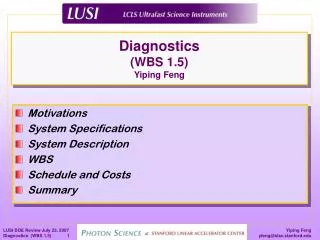
Outline • Diagnostics & common optics (DCO) overview • DCO scope • Components locations • Components physics requirements • Components descriptions • Deliverables • Schedule • Costs • Major risks • 6-month look-ahead • Summary
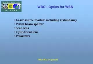
Overview • Common needs recognized for all LUSI instruments in • Diagnostics for measuring X-ray FEL properties • Transverse beam profile • Incident beam intensity • Transverse beam positions • Wave field at focus • Optical components for performing X-ray FEL manipulations • Beam size definition and clean-up • Attenuation • Pulse pattern selection and/or repetition rate reduction • Isolation of fundamental from high harmonics • Focusing • Monochromatization
Overview (cont.) • Common components identified among all LUSI instruments & categorized, based on functionalities, into • diagnostics suite • common optics suite • To facilitate common design & implementation • A single WBS element created – WBS 1.5 • Captured all XPP, CXI, and XCS common components • The DCO integrated team put in place • DCO scientific/technical team • DCO engineering team
DCO Science Team • Responsible for developing specifications and device/component concepts for DCO DCO scientific/technical team • Yiping Feng, DCO lead scientist • Instrument liaisons & DCO scientists • David Fritz, XPP instr., attenuator, harmonic rejection mirrors • Marc Messerschmidt, XPP instr. • Sébastien Boutet, CXI instr., slits system, pulse picker • Aymeric Robert, XCS instr., focusing lens, offset monochromator • Niels van Bakel, X-ray detectors support • Gunther Haller/Dieter Freytag, EE support
Overview (cont.) • Physics requirement documents released by DCO team • Diagnostics • sp39100004-1_XRPopInProfMon-PRD • sp39100009-1_XRPopInIntensity-PRD • sp39100008-1_XRIntensity-Position-PRD • sp39100007-0_XRWavefrontMon-PRD* • Common optics • sp39100011-1_BeLens-PRD • sp39100014-1_Slits-PRD • sp39100010-1_Atten-PRD • sp39100023-1_Pulse_Picker-PRD • sp39100034-1_HarmRejMirror-PRD • sp39100016-0_OffsetMono (in work)* * In initial version-0
DCO Scope • Work Breakdown Structure
Components Locations • Components locations • Distributed throughout the XPP, CXI, and XCS instruments, including X-ray transport tunnel HEDS CXI Endstation X-ray Transport Tunnel XCS Endstation Near Experimental Hall XPP Endstation Far Experimental Hall LCLS X-ray FEL SXR AMO
Components Locations (cont.) • An example in XPP • 15 diagnostics/common optics components embedded in XPP
Device/Component Counts • Total device/component counts
DCO Physics Requirements • Goals • Build diagnostics and common optics to help XPP, CXI, and XCS instruments achieve their full scientific potentials • Common requirements stemmed from characteristics of LCLS X-ray FEL • Ultra short @ 100 fs, and repetition rate of 120 Hz • High peak power ~ 10 GW • Fully coherent in transverse directions ~ TEM00 • Intrinsic intensity, temporal, spatial, timing fluctuations on per-pulse basis, i.e.,
DCO Physics Requirements (cont.) • Unique challenges identified for LUSI DCO • Capable of sustaining the instantaneous LCLS X-ray FEL peak power • Exercising deliberate material selection • Thermal calculations including melting threshold and onset of thermal fatigue • Capable of coherent beam manipulation • Minimizing large angle diffractions to the extent possible • i.e., utilizing cylindrical blades for slits • Minimizing random wavefront distortion to the extent possible • Reducing surface roughness and bulk non-uniformities • Capable of ultra-fast signal detection • Extracting signals in ~ ns to avoid large background • i.e., charge-sensitive detection in intensity measurements • Capable of per-pulse measurement if required • Each pulse is a new experiment • Averaging NOT an option, requiring high S/N ratio from single pulse • i.e., high-precision intensity measurements to 0.1% based on single pulse
Linac-to-Undulator (227m) Undulator Hall (175m) Near Expt. Hall X-ray Transport (230m) Far Expt. Hall 60 mm 1.1 mrad 220 mm 490 mm Mono location 200 m Rayleigh Length 54 m XPP - 193 m XCS - 419 m Source to Sample distance @ 1.5 Å CXI - 440 m DCO Physics Requirements (cont.) • Unique challenges for LUSI DCO (cont.) • Capable of maintaining ultra-high mechanical stability in case of large optics-to-sample distance, i.e., XCS offset monochromator • To 10% of beam size at 50 mm 0.25 mrad pointing stability
Diagnostics suite Pop-in profile monitor (WBS 1.5.2.1) Requirements Destructive; Retractable; Variable FOV and resolution At 100 mm resolution, 24x24 mm2 FOV; At 8 mm resolution, 2x2 mm2 FOV; Capable of per-pulse op. @ 120 Hz if required Attenuation used if necessary Pop-in intensity monitor (WBS 1.5.2.2) Requirements Destructive; Retractable; Relative accuracy < 1%; Working dynamic range 100; Sensitive area 20x20 mm2 Capable of per-pulse op. @ 120 Hz Attenuation used if necessary Component Descriptions
Diagnostics suite (cont.) Intensity-position monitor (WBS 1.5.2.3) Requirements In-situ, but retractable if desired Highly transmissive (< 5% loss); Relative accuracy < 0.1%; Working dynamic range 1000; Position accuracy in xy < 10 mm; Per-pulse op. at 120 Hz; Wavefront monitor (WBS 1.5.2.1) Requirements In-situ, but retractable if desired Variable FOV and resolution Per-pulse op. @ 120 Hz Attenuation used if necessary Computational algorithms needed for wavefront reconstruction Component Descriptions (cont.)
Common optics suite X-ray focusing lenses (WBS 1.5.3.2) Requirements Produce variable focused spot size For XPP 2-10 mm in focus 40-60 mm out-of-focus Minimize wavefront distortion Withstand FEL full flux Slits system (WBS 1.5.3.3) Requirements 0 – 10 mm gap setting 10-9 in trans. btw 2-8.265 keV 10-8 in trans. at 25 keV Gap precisions in xy 0.5 mm for precise slits 5 mm for coarse slits Minimize diffraction/wavefront distortion Withstand FEL full flux Component Descriptions (cont.)
Pulse picker (WBS 1.5.3.5) Requirements < 3 ms switching time Reduce rep rate < 10 Hz operation* Not preferred for > 10 Hz continuous operation, FEL rep rate reduction will be used Withstand full LCLS FEL flux Requiring 100 mm Si3N4 to protect the steel blade Common X-ray optics (cont.) Attenuators (WBS 1.5.3.4) Requirements Minimize wavefront distortion Withstand full FEL flux 108 attenuation at 8.3 keV* 104 attenuation at 24.9 keV At least 3 steps per decade Component Descriptions (cont.) *DCO key performance parameters
Offset monochromator (WBS 1.5.3.1) Requirements Large 600 mm offset 6-25 keV energy range Continuously tunable 10% positional stability (of beam size) Double-crystal geometry Attenuation used if necessary Common optics (cont.) Harmonic rejection mirrors (WBS 1.5.3.6) Requirements Energy range btw 6 - 8.265 keV 104 contrast ratio between fundamental and the 3rd harmonic, 106 overall 80% overall throughput for the fundamental Minimize wavefront distortion Withstand full FEL flux Component Descriptions (cont.)
DCO Deliverables • Phased deliverables
DCO Schedule • WBS 1.5 schedule developed to ensure that instruments’ milestones are met on time • Preliminary design reviews • Pop-In Profile Monitor Q4 FY08 • Pop-In Intensity Monitor Q4 FY08 • Pulse Picker Q4 FY08 • Slits System Q1 FY09 • Intensity-Position Monitor Q1 FY09 • X-ray Focusing Lens Q2 FY09 • Attenuators Q3 FY09 • Harmonic Rejection Mirrors Q4 FY09 • Wavefront Monitor Q1 FY10 • Offset Monochromator Q2 FY10 • Final design reviews • Pulse Picker Q1 FY09 • Slits System Q1 FY09 • Intensity-Position Monitor Q2 FY09 • Pop-In Profile Monitor Q2 FY09 • Pop-In Intensity Monitor Q3 FY09 • X-ray Focusing Lens Q3 FY09 • Attenuators Q4 FY09 • Harmonic Rejection Mirrors Q1 FY10 • Wavefront Monitor Q2 FY10 • Installation complete • CD-4A Installation complete Q1 FY11 • CD-4B Installation complete Q3 FY11 • CD-4C Installation complete Q3 FY12
DCO Cost Baseline • Labor & non-labor (M&S, etc.)
DCO Cost Baseline (cont.) • Level-3/4 cost breakdown • 1.5.02 - Diagnostics • 1.5.03 – Common optics
DCO Major Risks • Offset monochromator • Mechanical stability not met • Required to maintain position stability to 10% of beam size • Mitigation • Ensure requirements are clearly stated and agreed prior to award and fabrication • Implement a stringent vendor selection process • Implement regular visits to vendor • Implement frequent and measurable status reports • Maintain constant communication with the vendor prior to and during design and fabrication Linac-to-Undulator (227m) Undulator Hall (175m) Near Expt. Hall X-ray Transport (230m) Far Expt. Hall 60 mm 1.1 mrad 220 mm 490 mm Mono location 200 m Rayleigh Length 54 m XPP - 193 m XCS - 419 m Source to Sample distance @ 1.5 Å CXI - 440 m
6-Month Look-ahead • Major milestones • Preliminary design reviews • Q4FY08 – PDR Pop-in profile monitor • Q4FY08 – PDR Pop-in intensity monitor • Q4FY08 – PDR Pulse picker • Q1FY09 – PDR Intensity-position monitor • Q1FY09 – PDR Slits system • Final design reviews • Q1FY09 – FDR Slits system • Q1FY09 – FDR Pulse picker
Summary • Diagnostics and common optics help support LUSI instruments to fulfill CD-0 mission in a wide variety of cutting edge research capabilities • Diagnostic & optical components concepts are based on proven developments made at SPPS, FLASH, and SR sources • Safety hazards have been identified in Hazard Analysis Report (HAR) • Safety issues are considered at every step of design and fabrication process • Scope of DCO components for XPP, CXI, and XCS instruments fully defined • Resource loaded schedule developed through end of project • Preliminary designs of key components are well advanced • DCO and LUSI are ready for CD-2 approval