Download
1 / 41
420 likes | 461 Vues
ENM208. MILLING OPERATION Dr. Mümtaz ERDEM. ANADOLU ÜNİVERSİTESİ Industrial Engineerng Department. Manufacturing Processes. Milling Operations.

E N D
ENM208 MILLING OPERATION Dr. Mümtaz ERDEM ANADOLU ÜNİVERSİTESİIndustrial Engineerng Department
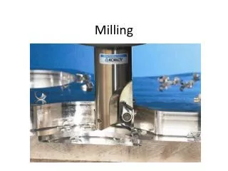
Manufacturing Processes Milling Operations Milling is another basic machining process by which surface is generated progressively by the removal of chips from a work piece as it is fed a rotating cutter. Multiple-tooth cutter is used so that the material removal rate is high. Good surface finish can be obtained in milling operations. Milling is particularly well suited and widely used for mass-production work. The cutting tool used in milling is known as aMilling Cutter. Spring 2005
Manufacturing Processes Milling Classifications Milling operations can be classified into three categories: 1. Peripheral Milling 2. Face Milling 3. End Milling Spring 2005
Manufacturing Processes Face Milling The generated surface is at right angles to the cutter axis and is the combined result of actions of the portions of the teeth located on both periphery and the face of the cutter. Most of the cutting is done by the peripheral portions of the teeth, with the face portions providing some finishing actions. Spring 2005
Manufacturing Processes Peripheral Milling The surface is generated by teeth located on the periphery of the cutter body. The surface generated is parallel with the axis of rotation of the cutter Both flat and formed surfaces can be produced by this operation Spring 2005
Manufacturing Processes End Milling The cutter usually rotates on an axis perpendicular to the workpiece, although it can be tilted to machine tapered surfaces. Flat surfaces as well as various profiles can be produced by end milling. End milling cutter diameter is less than the width of the workpiece. Spring 2005
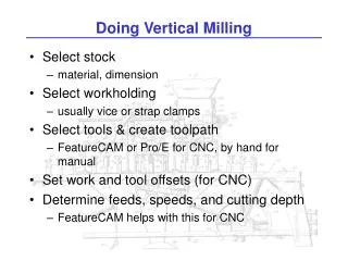
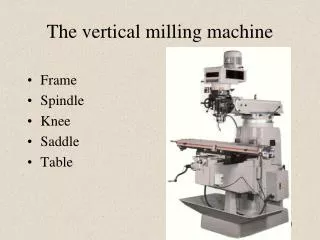
Manufacturing Processes Milling Machines • The milling machine supplies an accurate rotating spindle for the cutter and a table (vise) to fix and position the work part. There are two types of machines • Horizontal milling machines: • - Horizontal spindle • Designed for peripheral milling operations • Vertical milling machines: • - Vertical spindle • - Designed for face and end milling operations Spring 2005
Manufacturing Processes Vertical Milling Machine Spring 2005
Manufacturing Processes Horizontal Milling Machine Spring 2005
Manufacturing Processes Up Milling • Up milling: • Also called conventional milling, • Wheel rotation opposite of the feed. • The chip formed by each cutter tooth starts out very thin and increases its thickness. • The length of the chip is relatively longer. • Tool life is relatively shorter. • Need more clamping force to hold the work part. Spring 2005
Manufacturing Processes Down Milling Down milling: Also called climb milling, Wheel rotation is parallel to the feed The chip formed by each cutter tooth starts out thick and leaves out thin The length of the chip is relatively short Tool life is relatively longer Need less clamping force to hold the work part Spring 2005
Manufacturing Processes Peripheral Milling Positions Spring 2005
Manufacturing Processes Face Milling Positions Spring 2005
Manufacturing Processes Milling Calculations Select Cutting speed, V, and Feed per tooth, ft, from Machining Data Handbook. The RPM of the spindle is calculated as Where Ns = Rotational speed of the spindle (rpm) V = Surface speed (m/min) D = the cutter diameter Spring 2005
Manufacturing Processes Milling Calculations The depth of cut, DOC, is simply the distance between the old and new machined surface (mm). The width of cut, W, is the width of the cutter or work (mm). The feed speed, fm, of the table is related to the amount of metal each tooth removes during a revolution Where fm = Table feed speed (mm/min) ft= feed per tooth (mm/tooth) n = number of teeth on the cutter (tooth/r) Spring 2005
Manufacturing Processes Milling Calculations The cutting time can be calculated as For peripheral milling WhereTm = cutting time (min) L = Length of cut (mm) LA = Approach length (mm) Spring 2005
Manufacturing Processes Milling Calculations For Face milling WhereTm = cutting time (min) L = Length of cut (mm) LA = Approach length (mm) Lo = Overtravel length (mm) Spring 2005
Manufacturing Processes Milling Calculations The metal removal rate is calculated from Ignoring LA and Lo and substitute for Tm, gives (mm3/min) Spring 2005
Manufacturing Processes Milling Cutters The cutting tool used in milling is known as a milling cutter, the cutting edges called teeth. Types of milling cutters are related to the milling operations and can be classified as • Plain milling cutters • Form milling cutters • Side milling cutters • End milling cutters • Face milling cutters • Angle mıllıng cutters • T-slot cutters • Woodruff keyseat cutters Spring 2005
Manufacturing Processes Plain Milling Cutters Used in peripheral milling operations - Cylindrical or disk shaped - Have several straight or helical teeth on periphery - Used to mill flat surfaces Plain milling Cutter Spring 2005
Manufacturing Processes Form Milling Cutters Another peripheral milling cutter - Teeth ground to a special shape to produce a surface having a desired transverse contour, convex, concave shape. Rounding Corner Milling Cutter Convex milling Cutter Concave milling Cutter Spring 2005
Manufacturing Processes Side Milling Cutters • Similar to plain milling cutters • Teeth extend radial part way across one or both ends of cylinder toward the center • - Relatively narrow Spring 2005
Manufacturing Processes End Milling Cutters • Looks like a drill, but it has teeth on • the end as well as the periphery. • Have multiple teeth • Used in milling slots, profiling and facing narrow surfaces. • Have either straight or tapered shanks for smaller and larger cutter sizes, respectively. • End mills are also available with hemispherical ends (ball nose) for machining curved surfaces. Spring 2005
Manufacturing Processes Face Milling Cutters - Have teeth on periphery and both sides - Have a center hole so that they can be arbor mounted. - Widely used in both horizontal and vertical spindle machine tools - Available in a wide variety of sizes (diameters and heights) and geometries. Spring 2005
Manufacturing Processes Angle Milling Cutters Angle milling cutters are made in two types: Single-angle and double angle. Angle cutters are used for milling slots of various angles or milling the edges of workpieces to a desired angle Single-angle Cutters have teeth on the conical surface, usually at an angle of 45 or 60o to the plane face. Double-angle Cutters have V-shaped teeth, with both conical surfaces at an angle to the end faces. Spring 2005
Manufacturing Processes T-Slot Cutters • Have teeth on periphery and both sides • Used for milling the wide groove of a T-slot. • In order to use them, a vertical groove must first be made with a slotting mill or an end mill to provide a clearance for the shank. • - T-slot cutter must be fed carefully, because it cuts in 5 surfaces Spring 2005
Manufacturing Processes Woodruff Keyseat Cutters Woodruff keyseat cutters are made for the single purpose of milling the semi-cylindrical seats required in shafts for woodruff keys They come in standard sizes corresponding to woodruff key sizes. Spring 2005
Manufacturing Processes Shaping Operations Shaping uses straight line cutting motion with a single point cutting tool to generate flat surfaces The workpiece is fed at right angles to the cutting motion between successive strokes of the tool. The cutting tool is held in the tool post located in the ram, which reciprocates over the work with a forward stroke (cutting stroke), and quick return stroke (non cutting stroke) Spring 2005
Manufacturing Processes Shaping Machine (Shaper) Spring 2005
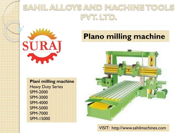
Manufacturing Processes Planing Operation The workpiece is mounted on a table that travels along a straight path. A horizontal cross-rail, which can be moved vertically along the ways in the column, is equipped with one or more tool heads. The cutting tools are attached to the heads, and machining is done along a straight path. Planing is usually done on large workpieces – as large as 25 m X 15 m Spring 2005
Manufacturing Processes Planing Machine (planer) Spring 2005
Manufacturing Processes Shapes produced by shaping and planing operations In addition to plain flat surfaces, the shapes most commonly produced on the shaper and planer are shown below Spring 2005
Manufacturing Processes Broaching Operation • Linear Tool Motion (Like Shaping) • Single Pass • Multiple Teeth • Successive Cutting Steps • Custom Shaped Geometry • Need Existing Hole for Internal Shapes Broaches are used in production to finish holes, splines, and flat surfaces Spring 2005
Manufacturing Processes Abrasive Machining Operations Abrasive machining is a material-removal process that involves the interaction of abrasive grains with the workpiece at high cutting speeds and shallow penetration depths. In many cases in manufacturing, the surface finish and dimensional accuracy requirements for a part are too fine, the workpiece material is too hard, or the workpiece material is too brittle. One of the best methods for producing such parts is abrasive machining Abrasive is a small, nonmetallic hard particle having sharp edges and an irregular shape (unlike the cutting tools described previously). Abrasives are capable or removing small amounts of material from a surface through a cutting process. Spring 2005
Manufacturing Processes Abrasive Machining Operations Spring 2005
Manufacturing Processes Surface Grinding Operation Horizontal spindle and reciprocating table grinding machine Surface grinding are used to grind flat surfaces Spring 2005
Manufacturing Processes Surface Grinding Operation Vertical spindle and reciprocating table grinding machine Surface grinding are used to grind flat surfaces Spring 2005
Manufacturing Processes External Cylindrical Grinding Operation Cylindrical Grinding is commonly used for producing external cylindrical surfaces. The grinding wheel revolves at an ordinary cutting speed, and the workpiece rotates on centers at a much slower speed. The grinding wheel and the workpiece move in opposite directions at their point of contact. Spring 2005
Manufacturing Processes Internal Cylindrical Grinding Operation Internal Grinding is commonly used for producing internal cylindrical surfaces (holes). The grinding wheel revolves at an ordinary cutting speed, and the workpiece rotates on at a much slower speed. The grinding wheel and the workpiece move in opposite directions at their point of contact. Spring 2005
Manufacturing Processes Abrasives Spring 2005
Manufacturing Processes Grinding Wheel Identification Most grinding wheels are identified by a standard marking system that has been established by the American National Standards Institute (ANSI) Spring 2005