Download
1 / 84
851 likes | 1.37k Vues
Figure 3.1 Decision-making tree: transferring to a higher level of care. Figure 3.2 Series resistors with a single unknown current i s . Figure 3.3 A simplified version of the circuit shown in Fig. 3.2. Figure 3.4 The black box equivalent of the circuit shown in Fig. 3.2.

E N D
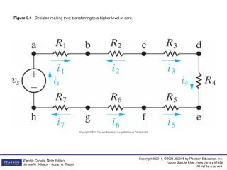
Figure 3.1 Decision-making tree: transferring to a higher level of care.
Figure 3.2 Series resistors with a single unknown current is.
Figure 3.3 A simplified version of the circuit shown in Fig. 3.2.
Figure 3.4 The black box equivalent of the circuit shown in Fig. 3.2.
Figure 3.7 Replacing the four parallel resistors shown in Fig. 3.5 with a single equivalent resistor.
Figure 3.10 A simplification of the circuit shown in Fig. 3.9.
Figure 3.11 The circuit of Fig. 3.10(b) showing the numerical value of is .
Figure 3.12 (a) A voltage-divider circuit and (b) the voltage-divider circuit with current i indicated.
Figure 3.17 A simplification of the circuit shown in Fig. 3.16.
Figure 3.21 An ammeter connected to measure the current in R1 and a voltmeter connected to measure the voltage across R2.
Figure 3.22 A short-circuit model for the ideal ammeter, and an open-circuit model for the ideal voltmeter.
Figure 3.23 A schematic diagram of a d’Arsonval meter movement.
Figure 3.28 A resistive network generated by a Wheatstone bridge circuit.
Figure 3.29 A ∆ configuration viewed as a π configuration.
Figure 3.34 A transformed version of the circuit shown in Fig. 3.32.
Figure 3.35 The final step in the simplification of the circuit shown in Fig. 3.32.