Getting started in high performance electronic design
600 likes | 790 Vues
Getting started in high performance electronic design . Wojtek Skulski Department of Physics and Astronomy University of Rochester Rochester, NY 14627-0171 skulski _at_ pas.rochester.edu First presented May/23/2002 Updated for the web July/03/2004. The goal and outline of this class.

Getting started in high performance electronic design
E N D
Presentation Transcript
Getting started in high performance electronic design Wojtek Skulski Department of Physics and Astronomy University of Rochester Rochester, NY 14627-0171 skulski _at_ pas.rochester.edu First presented May/23/2002 Updated for the web July/03/2004
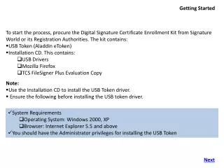
The goal and outline of this class • Goal: • Describe the tools available to us for designing high performance electronic instruments. • Outline • Why do we need surface mount and multilayer boards? • What tools and resources are available? • How to get my PCB manufactured? • How to get my board assembled? • Designing with OrCAD Capture and OrCAD Layout. • The audience • You know the basics of electronics. • … and you need to get going quickly with your design.
Disclaimer • I am describing tools and methods which work for me. • I do not claim that this information is complete. • My methods are not necessarily the best ones.
The key to high performance boards High performance =surface mount technology+ground and power planes
A high-performance electronic board(I developed it using OrCAD) • Surface mount technology (SMT) parts on both sides of the PCB. • Two inner planes (ground and power) and two signal routing planes. • Controlled impedance copper traces. • Minimum trace width and spacing 7 mils. • Solder mask (top and bottom) and silkscreen legend (top and bottom). JTAG connector Delay chips 28 J-pins ECL IN CAMAC interface chip 208 pins NIM OUT CAMAC connector ECL OUT
Good board => good performance • The board contributes only 5 ps (RMS) to the width of the peaks. • Light will travel only 1.5 mm during 5 ps! • It cannot be done any better with this particular chipset. Delay range 2.5 ns
Why do we need surface mount? • Self-inductance and mutual inductance are both proportional to the area of the circuit. • The size of SMT parts is much smaller than the size of leaded parts. • The area of the SMT circuitry is therefore smaller. • The SMT circuit can handle higher frequencies than a traditional circuit can. Larger area Smaller area
Why do we need ground and power planes? • At low frequencies the return current follows the path of least resistance. • At high frequencies the return current follows the path of least inductance… • … if there is one! • Small area low inductance & low crosstalk we need ground and power planes. Source Load Current density profile i(d) = 1/[1+(d/h)2] See “Black magic” chapter 5 h d
Resources LiteratureSoftwareElectronic partsManufacturing and assembly
Selected books and Application Notes(sometimes they give conflicting advice!) • Book: High Speed Digital Design: A Handbook of Black Magic, ISBN 0-13-395724-1. • Analog Devices www.analog.com • Book: “Practical Analog Design Techniques”, section 9 “Hardware Design Techniques” • AN-280 “Mixed Signal Circuit Techniques” • AN-333 “Design and layout of a video graphic system for reduced EMI” • Texas Instruments www.ti.com • sloa089 “Circuit Board Layout Techniques” • sdya009c “Designing With Logic” • Xilinx www.xilinx.com • Signal Integrity Central • UG002 “Virtex-II Platform FPGA Handbook” page 464 “PCB Considerations” • ON-Semi (former Motorola Semiconductor Division) www.onsemi.com • AND8020/D “Termination of ECL Logic Devices”
Web resources • Analog Devices Seminar Materials www.analog.com • Texas Instruments Application Notes www.ti.com • National Semiconductors, Linear Technology, On-Semi, etc. • Jan Axelson’s Lakeview Research • www.lvr.com - serial & parallel port programming, USB, assembly techniques, etc. • Entry-level to mid-professional information, very well presented. • List of electronic design software • www.terrypin.dial.pipex.com/ECADList.html - case sensitive URL. • Comprehensive EE websites • www.engr.unl.edu/ee/eeshop/netsites.html - many useful links. • www.epanorama.net - links to design software, soldering techniques, etc.
What design software is available to UofR users? • OrCAD • Popular, proven, available on campus. • Not easy to learn, some quirks and bugs. • Powerful enough for me: up to 16 layers. I designed my boards with OrCAD. • Annual “small maintenance fee” shared among power users (EE, CS, Physics). • Websites: www.orcad.com, www.cadence.com • If OrCAD is not enough for you • You can install other more powerful Cadence software from the same CD’s. • If OrCAD is too complex for you, then try free ExpressPCB • Easy, you can learn it quickly. • Built-in part procurement info (DigiKey part numbers). • Results are limited: 2 or 4 layers, non-standard CAM output. • Aimed at hobby projects. Use it to design simple instruments. • Websitewww.ExpressPCB.com- both the software and PCB fabrication.
Other electronic design software • Free design software for Linux/Unix/Windows, up to 8 layers, GERBER output • Buyer beware: this is free open source software. Hacking is required! • Schematic:xcircuit.ece.jhu.edu • PCB layout:pcb.ece.jhu.edu • Eagle www.cadsoftusa.com • Professional, about $1k per user with University discount. • Free limited version is available (limited to only two layers and 10x8 cm). • Protel www.protel.com • Professional, rather expensive, 30-day unlimited trial version available. • Design software from DigiKey or Jameco. • Relatively cheap, I do not know the quality. • Comprehensive list of electronic design software • www.terrypin.dial.pipex.com/ECADList.html(case sensitive URL)
Where to find parts and tools? • DigiKey.com. • I order most parts from DigiKey (capacitors, resistors, etc.). • Other distributors. • Avnet, Newark, Arrow, Nu Horizons, Jameco, ... • Directly from manufactures. • Analog Devices, Texas Instruments, Cypress, Linear, National Semi, On-Semi, ... • Part Miner can help locate a part. • Website with a search engine: www.FreeTradeZone.com. • Sometimes I buy tools (but not parts) from Ebay. • I bought a DVM and an oscilloscope on Ebay. • Sometimes one can even buy OrCAD and other ECAD software. • Buying on Ebay requires patience.
How to have your PCB manufactured? • Sierra Proto Express www.2justforyou.com • High quality, excellent promotions. • Very fast turnaround. • They accept CAM design files via internet, GERBER format. • They manufactured all my PCBs. I am happy with the result. • PCBExpress • Similar to Sierra Proto Express. • ExpressPCB • Only 2 or 4 layers. • You have to use their PCB design software, which is rather limited. • Suitable for simple projects or hobby. • Other companies • I have no experience with other companies. • Website with many links: www.lvr.com/pcbs.htm
How to have your SMT board assembled? • Do it yourself, it is not very difficult! • Good light, fine pincers. • Use 1206 footprints for your first SMT board. They are easy to handle. • Edroy Stereoscopic OpticAid +7D (2.75x magnification). • Edroy model 717. Distributor:www.scslimited.com, 1 (800) 749 8425. • 15W RadioShack grounded iron works fine. • The iron has to be either grounded or “ESD safe”. Avoid anything else. • Water-soluble flux is essential when soldering multipin chips! • There are a few other tricks with multipin chips (talk to me). • Hildy Licht company does it routinely. • www.hildy.com
Designing with OrCADSchematic CapturePCB LayoutManufacturing
Find the bugs before they bite you • Schematic drawings are more than just drawings. • Connections have to satisfy Design Rules. • Capture can automatically locate violations (Design Rules Check). • The netlist is passed to Layout only after all violations are corrected. • PCBs are more than just drawings, too. • There can be accidental electric shorts and part-to-part spacing violations. • Layout can automatically locate such problems. • CAM files are created after correcting (or ignoring) all such violations. • Before the board is manufactured. • CAM files need to be suitable for your manufacturer (check with them!). • Ideally: PSpice simulation using actual board layout (I have not done this). • Ask (and pay) for the electrical check of your boards during manufacturing.
What to expect from the design software? • Schematic design. • Convenient drawing capabilities. • Easy creation of new schematic symbols. • Automatic design rule checking. • Support for properties such as footprints, manufacturer part numbers, etc. • Netlist creation from schematics. • Access to schematic part database (but can live without it). • Board layout. • Multi layer: at least 4 layers, possibly 10 layers or more. • Support for ground and power planes. • Narrow traces: down to 7 mils, possibly down to 4 mils. • Output files in a format suitable for manufacturing: GERBER format. • Automatic checking design rules, spacing violations, etc. • Good libraries of standard footprints. • Easy creation of new footprints. • Optional: a good autorouter can be very useful. • Schematic layout integration (ECO, back and forth annotation).
Interactive Capture and Layout tutorials • Capture tutorial directory …/Cadence/Capture/Tutorial • Layout tutorial directory …/Cadence/Layout_Plus/Tutorial • …but you will also need printed manuals.
Design flow: schematic, layout, actual board • Software has to manage the consistency between the schematic and the layout. • Photoplotter CAM files are used to manufacture the physical board. Actual board Schematic Capture PCB Layout
Schematic symbols are the building blocks • Physical parts are represented by “schematic symbols”, which have properties. • Visible properties: value (e.g., 5 kohms), schematic reference (e.g., R11). • Invisible properties: footprint (1206, 0805, etc), distributor number (P24.9CCT-ND). • Invisible properties are essential both for Layout and for the procurement. • I used to manage invisible properties “by hand” using the property editor. Managing properties “by hand” Symbols “as seen” in Capture
Capture provides many schematic symbols • Schematic symbols can be picked from libraries. • NB: distributor part numbers of actual parts are not provided in the libraries. List of available libraries Symbols already placed on a schematic page
Where to find actual parts and their “properties”? • I mostly use the hardcopy DigiKey catalog. • Their distributor part code looks something like P24.9CCT-ND. • I type this code as an “invisible user property” named PARTNO. • I print the PARTNO with the bill-of-materials (BOM). A page from the DigiKey catalog
Often Capture does not provide the symbol that you need… • For example, Analog Devices opamp type AD830 is not there. • I have to make the symbol for it. Symbol which was provided: AD829 Here I am constructing a new symbol AD829_0, which I will later rename to AD830 which I need.
CaptureCIS provides tools for managing the part database • CIS means “component information system”, which is a terrific idea. • It would be very helpful for managing the actual part database. • I have not used it yet. CIS access window, unfortunately empty. (I have not used it yet.)
Symbols + connections = schematic • In addition to properties, symbols also have pins. • Pins are connected with wires in order to form a netlist. • The netlist turns a loose collection of parts into the schematic. • The netlist can be written to disk. Layout will read it from there. • The PCB layout program will turn connections into copper traces. Individual symbols Schematic
Connections do not have to be drawn explicitly • Connection is either explicit (drawing a wire) or implied (two wires with the same names are assumed to be connected). • As you can see, many wires are not drawn, but rather implied by name. For example, all the memory wires labeled in red red are implicitly connected to the “off page port” with the same name. • It is a matter of style. Wires are connected to this port Other off-page “ports”
A large schematic becomes a “project” • A small schematic can fit onto one page. • But a large one will take several pages. • We need to organize many such pages into one coherent schematic. • Many pages put together form a project. • Project is divided into folders. • Every folder contains schematic pages. • Wires and busses extend between pages. • The top level page connects all other pages. • There can be no unconnected wires or pins. • Automatic Design Rules Check enforces this, and many other things. Project name Folders Pages
The top-level schematic page • The top level page contains all other pages. • Wires and busses connect pages together. Connections between pages Individual pages
What did we learn thus far? • Schematic is more than just a drawing: a lot is going on behind the scenes. • Parts = symbols + properties. • Schematic = symbols + connections. • A connection can be either explicit (drawing a line) or implied by names. • A large schematic is broken into hierarchical parts (folders and pages). • Connections between hierarchical parts tie the whole design together. • There are Design Rules that one must obey. Capture can check the rules. • Capture can write the design to disk in a format, that Layout will understand. • There are many Capture features that I did not touch upon. My guess is that you do not need these features to design your first few boards. • In addition to OrCAD, there is other design software available to us. Make your own choice in case OrCAD offers too much or too little.
Layout: twelve steps to perfect boards • 1: Choose and/or prepare footprints. • 2-3: Place components. • 4-5: Route connections. • 6-10: Examine and clean up the layout. • 11-12: Prepare and submit photoplotter files.
Example board: 445 components, 1298 connections • Mixed signal: digital circuits and and low-noise analog on the same board. • Digital clock frequency up to 65 MHz. • Design goal: analog noise level no more than about 10-3 V • I will use this example to walk you through the design process.
Before you start: check manufacturing details • Look at the PCB manufacturer’s website, learn their specs. • What is the min/max size of holes? • Minimum PCB trace width and separation? • Minimum clearances? • Maximum board size? • Limitations concerning the board shape? • Required file format? (Most likely GERBER, but check.) • Etc. • Prepare your “board template” according to the specs.
Layout step 1: prepare the footprints • Choose footprints from one of many Layout libraries. • Some footprints need to be custom made. • It is a good idea to cleanup footprint labels at this step. Nonstandard footprint LEMO socket Standard footprint 1206-size component
Layout step 2: Netlist + board template = ratsnest • Layout will take an empty board template and the netlist from Capture. • You will see a somewhat depressing picture showed below. Ratsnest Component footprints “Ratsnest” of unrouted connections Board outline
Layout step 3: placing the components • Green: top side, red: bottom side of the board A few routed connections Board outline
Layout step 4: ground and power distribution • Blue: ground plane, violet: power plane (in negative) • Yellow: connections to the planes with “thermal reliefs” Dark is copper light is etched +3.3 V digital +1.8 V +3.3 V analog -5 V +5 V
Ground and power distribution cont. • The number of plane layers must be even. The planes have to be symmetric. Otherwise the board will warp. • Example: one GND and one PWR plane. • The PWR plane can be partitioned if there is more than one power source. • Example: +/- 5V, 1.8V and 3.3V digital, and 3.3V analog are all on the same plane. • GND plane can be partitioned between the analog and the digital grounds. • If you do not feel comfortable doing it, don’t! A solid ground plane may be the best. • Consult Analog Devices and Texas Instruments Application Notes for details. • Read “Black Magic” by Howard & Johnson. Signal GND PWR Signal
Ground and power distribution cont. • By definition, SMT components imply no holes. The connections to the GND and PWR planes need to be established. It can be done either automatically or manually. • This step is called “fanout” in OrCAD-speak.
Layout step 5: routing the connections • Routing connections “by hand” can yield good boards, but it is tedious. • I routed my boards entirely by hand. Top side Bottom side
Routing the connections with an autorouter • The autorouter may even work :-). • You need to fine tune parameters such as priority of nets to be routed. • Some manual cleanup is usually necessary. • Digital boards can be autorouted. • Analog boards are better suitable for hand routing. Example: 6 layers, 35 components, 286 connections, 3 minutes on Pentium 160 MHz.
Autorouter, continued Layout Plus has two autorouters: a “trial-and-error” router that is very slow, and a “SmartRoute” that uses simulated annealing. SmartRoute can route a digital board pretty fast. However, when it comes to an analog or mixed-signal boards, I am routing them by hand. Autorouting is an area of intense competition among ECAD companies. Autorouters keep improving, but do not expect miracles if you are laying out an analog board.
Layout step 6: cleaning up the silkscreens • Silkscreen tells you what is what on the board. It is very useful. • Grey: top, yellow: bottom. • NB: on the display the default Layout top color is white, not good. • Change it to grey.
Layout step 7: cleaning up assembly drawings • You need assembly drawings if someone else is assembling the board. • Blue: top, yellow: bottom. • By default, Layout makes extremely messy silkscreens and assembly drawings. • NB: this drawing was mostly cleaned, but not quite.
Layout step 8: cleaning up solder masks • Solder masks cover everything except places where you solder. • Violet: top, red: bottom. • Check it carefully, otherwise you will have to scrub the board. • It happened to me, look at the arrows! Two openings are missing in these spots
Layout step 9: cleaning up solder paste masks • Green: top, brown: bottom. • Only needed for automated assembly. • Not needed for hand assembly.
Layout step 10: examine photoplotter output • You will get what you send to the foundry! • Preview the rendition of the layers. This is your last chance to catch mistakes. • Watch for any mishaps (e.g., several close vias form a slit in the GND plane).
Layout step 11: create manufacturing files • Check with them which files and what format they need. • The following is “extended GERBER” accepted by Sierra Proto Express.
Optional “beautification” step • GERBER files can be examined and fine-tuned using the GerbTool utility. • Example: “teardropping” makes manufacturing easier. • You need to be a GERBER expert to know what GerbTool is doing. • I rarely perform such “beautifications” with my boards.