Diffraction
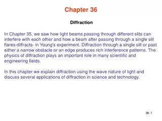
This explanation delves into the phenomenon of diffraction, illustrating how the wave nature of light leads to distinct interference patterns when light passes through apertures or encounters edges. Key concepts include single-slit diffraction, destructive and constructive interference, the impact of slit width on intensity patterns, and the significance of apparatus size in resolving images. We explore the principles of Fraunhofer and Fresnel diffraction and discuss the modulation of double-slit interference patterns by single-slit diffraction effects, providing a comprehensive understanding for learners.

Diffraction
E N D
Presentation Transcript
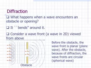
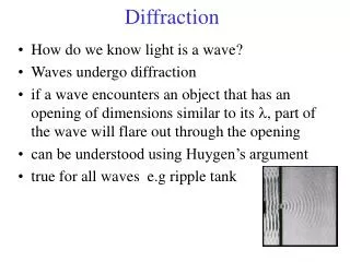
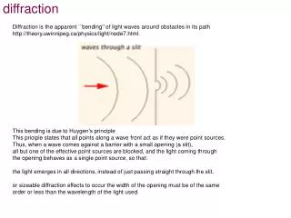
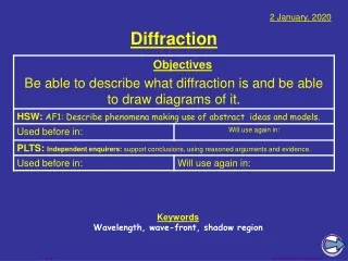
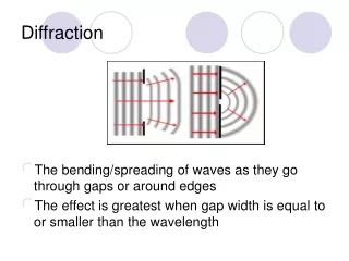
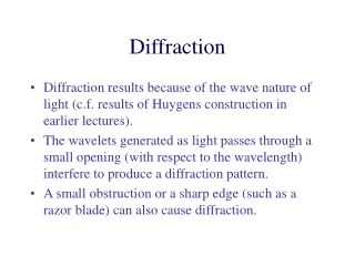
Diffraction • Diffraction results because of the wave nature of light (c.f. results of Huygens construction in earlier lectures). • The wavelets generated as light passes through a small opening (with respect to the wavelength) interfere to produce a diffraction pattern. • A small obstruction or a sharp edge (such as a razor blade) can also cause diffraction.
Single Slit Diffraction central fringe 1st minimum
destructive interference P1 r1 r2 a/2 P0 a/2 path difference incident light The light passing through each portion of the slit (of width a) will be in phase. The light at P0 will interfere constructively, producing the central maximum.
destructive interference P1 r1 r2 a/2 P0 a/2 path difference (x) incident light To find the first minimum we divide the slit into two equal parts a/2. The ray coming from the top of the upper portion (r1) will interfere with the light coming from the top of the lower portion (r2). The path difference will be x = (a/2) sin = /2 (for destructive interference) (1)
destructive interference P1 r1 r2 a/2 P0 a/2 path difference (x) incident light D For each ray r1 proceeding from the top portion there will be a ray r2 proceeding from the bottom portion with the same path difference as for the two rays shown. If D >> a, then the rays can be considered essentially parallel, and the two angles shown as are approximately equal.
The position of the first minimum is given by a sin = The position of the second minimum can be found by dividing the slit into 4 portions and proceeding as before. The general result is a sin = m, m is an integer for the positions of the minima. The maxima are found by assuming that they lie half way between the minima.
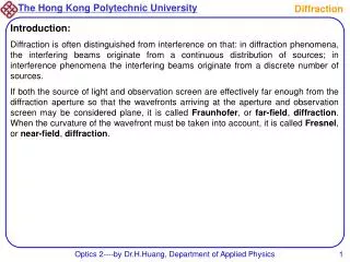
This result if for Fraunhoffer diffraction, where the assumption is made that the rays of light are approximately parallel. If the Fraunhoffer condition does not hold (i.e. the screen is very close to the slit) we have Fresnel diffraction, which is more difficult to describe mathematically
Intensity in Single-slit Diffraction The intensity in a single-slit diffraction pattern is given by where Im = the maximum intensity and
I (relative intensity) 1 a = 20 0 20 (degrees)
I (relative intensity) 1 a = 5 20 0 20 (degrees)
I (relative intensity) 1 a = 10 20 0 20 (degrees)
Diffraction by a Circular Aperture first minimum The first minimum can be found at sin = 1.22 /d (2) where d is the diameter of the circular aperture. Airy Disk
Resolution Equation (2) tells us that any circular aperture (such as a telescope or camera lens) will give a diffraction pattern. Each “object” in the field of view will give rise to such a diffraction pattern, and the image spot (diffraction pattern) will be smaller if the diameter of the aperture is larger. This is why larger telescopes (or microscopes) give better resolution. If we have control over the wavelength of light (for example we can illuminate a microscope slide with UV light) a smaller wavelength will lead to a smaller image spot and better resolution.
Rayleigh’s Criterion Rayleigh’s criterion quantifies resolution and is stated as: If the angular separation of two point sources is such that the central maximum from the diffraction pattern of one source is centered on the first minimum of the other, the two objects will just be resolved. For the objects to be resolvable their minimum angular separation is given by where R is in radians.
Diffraction by a Double Slit • In previous discussion of double slit interference we ignored the single slit diffraction effects produced by the individual slits. • This is reasonable if the width of the slits is much less than the wavelength of the illuminating light (see diagrams of intensity for single slit diffraction) as the central maximum will be large and of approximately constant brightness.
If this is not the case, the double slit pattern will be superimposed on the much broader single slit diffraction pattern. The bright central maximum will be crossed by the double slit interference pattern, but the intensity will still fall to zero where minima are predicted for single slit diffraction. In fact, the brightness of each bright fringe due to the double slit pattern will be “modulated” by the intensity envelope of the single slit pattern. The position of the double slit fringes is not changed, only the intensity is affected.
The intensity of the combined pattern (single-slit diffraction together with double-slit interference) is given by where d is the distance between the slits, while a is the width of the slits, and is the angle from the straight through position.