ANALOG TO DIGITAL CONVERTOR (ADC)
140 likes | 303 Vues
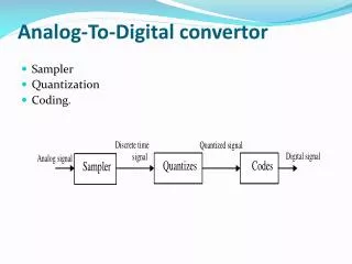
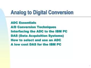
ANALOG TO DIGITAL CONVERTOR (ADC). Module Objective. Configure ADC for polled or interrupt operation Configure the control registers. Analog to Digital Convertor Module. 14 Channels with Multiplexed Input Linear Successive Approximation 8 bit resolution Single or Continuous Conversion

ANALOG TO DIGITAL CONVERTOR (ADC)
E N D
Presentation Transcript
Module Objective Configure ADC for polled or interrupt operation Configure the control registers
Analog to Digital Convertor Module • 14 Channels with Multiplexed Input • Linear Successive Approximation • 8 bit resolution • Single or Continuous Conversion • Conversion Complete Flag or Conversion Complete Interrupt • Selectable ADC Clock
ADC Signals • I/O Signals : 13 I/O pins (port B and D) • ADC Analog Power Pin (VDDA) • ADC Analog Ground Pin (VSSA) • ADC Voltage Reference Pin (VDDAREF) • Power supply for setting the reference voltage VREFH • ADC Voltage Reference High Pin (VREFH) • One of two reference supplies and is generated from VDDAREF with a value VDDAREF/2 • ADC Voltage Reference Low Pin (VLOW) • Lower Reference Supply for ADC • ADC Voltage In (ADVIN) • Input voltage signal from one of the fourteen channels
ADC Block Diagram INTERNAL DATA BUS Read DDRB/DDRD Disable Write DDRB/DDRD • • DDRBx/DDRDx RESET • • PTB/Dx Write PTB/PTD PTBx/PTDx (ADC Channel 1) • Read PTB/PTD • ADC Data Register Disable ADCH[4:0] ADC SuccessiveApproximationRegister Channel Select Interrupt Logic ADC Voltage In (ADVIN) Conversion Complete ADC Clock CGMXCLK COCO/IDMAS AIEN Clock Generator Bus Clock ADICLK ADIV[2:0]
ADC Registers • Three registers control and monitor ADC operations: • ADC status and control register (ADSCR) • ADC data register (ADR) • ADC clock register (ADCLK)
ADC Clock 0 0 0 0 READ: ADIV2 ADCLK ADIV1 ADIV0 ADICLK WRITE: RESET: 0 0 0 0 0 0 0 0 ADC Clock Register (ADCLK) • ADC Clock Presacler Bits (ADIV2:ADIV0) • Selects divide ratio used by ADC to generate internal ADC clock • ADC Input Clock Select (ADICLK) • Selects either bus clock or CGMXCLK as input clock source • 1 = Internal bus clock • 0 = External clock (CGMXCLK) • Please Note: Internal ADC Clock must not exceed 1MHz
ADC Status and Control READ: ADSCR COCO/ AEIN ADCO ADCH4 ADCH3 ADCH2 ADCH1 ADCH0 WRITE: IDMAS RESET: 0 0 0 1 1 1 1 1 ADC Status and Control Register (ADSCR) • Conversion Complete / Interrupt DMA Select (COCO/IDMAS) • Set when conversion is complete • Selects either CPU or DMA to service ADC interrupt request. • Cleared whenever ADC Status and Control Register is written or whenever the ADC Data Register is read. • 1 = Conversion completed(AEIN=0) / DMA Interrupt (AEIN=1) • 0 = Conversion not completed(AEIN=0) / CPU Interrupt (AEIN=1) • ADC Interrupt Enable(AEIN) • Interrupt at end of ADC conversion • 1 = ADC Interrupt Enabled • 0 = ADC Interrupt Disabled • ADC Continuous Conversion (ADCO) • 1 = Continuous ADC conversion • 0 = One ADC conversion • ADC Channel Select Bits (ADCH[4:0]) • Select one of fourteen channels • If all bits are set to one ADC subsystem is turned off
ADCH4 ADCH3 ADCH2 ADCH1 ADCH0 Input Select 0 0 0 0 0 ATD0, PTB0 0 0 0 0 1 ATD1, PTB1 0 0 0 1 0 ATD2, PTB2 0 0 1 1 0 ATD3, PTB3 0 0 1 0 0 ATD4, PTB4 0 0 1 0 1 ATD5, PTB5 0 0 1 1 0 ATD6, PTB6 0 1 1 1 ATD7, PTB7 0 ATD8, PTD5 0 1 0 0 0 ATD9, PTD4 0 1 0 0 1 ATD10, PTD3 1 0 1 0 0 ATD11, PTD2 0 1 0 1 1 ATD12, PTD1 0 1 1 0 0 ATD13, PTD0 0 1 1 0 1 Unused * 1 1 1 0 0 Unused * 0 1 1 1 1 Unused * 1 0 0 0 0 Unused * 1 0 0 0 1 0 0 1 0 Unused * 1 Unused * 1 0 0 1 1 Unused * 1 0 1 0 0 Unused * 0 1 0 1 1 Unused * 1 0 1 1 0 Unused * 1 0 1 1 1 Unused * 1 1 0 0 0 1 0 0 1 Unused * 1 1 1 0 1 0 Unused * 1 1 0 1 1 RESERVED ** 2*V 1 1 1 0 0 REFC 1 1 0 1 V 1 REFC 2*V 1 1 1 1 0 REFL [ADC power off] 1 1 1 1 1 ADC Channel Select
AD7 AD6 AD5 AD4 AD3 AD2 AD1 AD0 READ: ADR WRITE: RESET: X X X X X X X X ADC Result • ADC Data Register (ADR) • Contains 8-bit conversion result • Updated each time ADC conversion completes
- Low Power Modes - • WAIT • ADC module remains active • ADC registers are not accessible • Except to DMA • ADC module interrupt can wake MCU • STOP • ADC module is inactive • Any pending conversion is aborted • Conversions resume when MCU exits stop mode after an extenal interrupt • Allow one conversion cycle to stabilize the analog circuitry