Analog to Digital Conversion
Analog to Digital Conversion. ADC Essentials A/D Conversion Techniques Interfacing the ADC to the IBM PC DAS (Data Acquisition Systems) How to select and use an ADC A low cost DAS for the IBM PC. Why ADC ?. Digital Signal Processing is more popular Easy to implement, modify, … Low cost

Analog to Digital Conversion
E N D
Presentation Transcript
Analog to Digital Conversion ADC Essentials A/D Conversion Techniques Interfacing the ADC to the IBM PC DAS (Data Acquisition Systems) How to select and use an ADC A low cost DAS for the IBM PC
Why ADC ? • Digital Signal Processing is more popular • Easy to implement, modify, … • Low cost • Data from real world are typically Analog • Needs conversion system • from raw measurements to digital data • Consists of • Amplifier, Filters • Sample and Hold Circuit, Multiplexer • ADC Chap 0
Basic I/O Relationship ADC is Rationing System x = Analog input / Reference Fraction: 0 ~ 1 n bits ADC Number of discrete output level : 2n Quantum LSB size Q = LSB = FS / 2n Quantization Error 1/2 LSB Reduced by increasing n ADC Essentials Chap 0
Offset Error Gain Error Can be eliminated by initial adjustments Integral Linearity Error Differential Linearity Error Nonlinear Error Hard to remove Converter Errors Chap 0
Converter Resolution The smallest change required in the analog input of an ADC to change its output code by one level Converter Accuracy The difference between the actual input voltage and the full-scale weighted equivalent of the binary output code Maximum sum of all converter errors including quantization error Conversion Time Required time (tc) before the converter can provide valid output data Converter Throughput Rate The number of times the input signal can be sampled maintaining full accuracy Inverse of the total time required for one successful conversion Inverse of Conversion time if No S/H(Sample and Hold) circuit is used Terminologies Chap 0
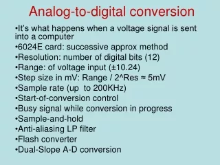
Input voltage change during the conversion process introduces an undesirable uncertainty Full conversion accuracy is realized only if this uncertainty is kept low below the converter’s resolution Rate of Change x tc resolution Example 8-bit ADC Conversion Time: 100sec Sinusoidal input Rate of change Let FS = 2A Limited to Low frequency of 12.4 Hz Few Applications More on Conversion Time Chap 0
S/H (Sample and Hold) Analog circuits that quickly samples the input signal on command and then holds it relatively constant while the ADC performs conversion Aperture time (ta) Time delay occurs in S/H circuits between the time the hold command is received and the instant the actual transition to the hold mode takes place Typically, few nsec Example 20 nsec aperture time Reasonably good for 100sec converter S/H increase Performance Chap 0
Typically, Differential or Single-ended input signal of a single polarity Typical Input Range 0 ~ 10V and 0 ~ 5V If Actual input signal does not span Full Input range Some of the converter output code never used Waste of converter dynamic range Greater relative effects of the converter errors on output Matching input signal and input range Prescaling input signal using OP Amp In a final stage of preconditioning circuit By proportionally scaling down the reference signal If reference signal is adjustable Analog Input Signal Chap 0
Using unipolar converter when input signal is bipolar Scaling down the input Adding an offset Bipolar Converter If polarity information in output is desired Bipolar input range Typically, 0 ~ 5V Bipolar Output 2’s Complement Offset Binary Sign Magnitude … Input signal is scaled and an offset is added Converting bipolar to unipolar Add offset scaled Chap 0
I/O of typical ADC ADC output Number of bits 8 and 12 bits are typical 10, 14, 16 bits also available Typically natural binary BCD (3½ BCD) For digital panel meter, and digital multimeter Errors in reference signal From Initial Adjustment Drift with time and temperature Cause Gain error in Transfer characteristics To realize full accuracy of ADC Precise and stable reference is crucial Typically, precision IC voltage reference is used 5ppm/C ~ 100ppm/C Outputs and Analog Reference Signal Chap 0
Start From CPU Initiate the conversion process BUSY / EOC To CPU Conversion is in progress 0=Busy: In progress 1=EOC: End of Conversion HBE / LBE From CPU To read Output word after EOC HBE High Byte Enable LBE Low Byte Enable Control Signals Chap 0
A/D Conversion Techniques • Counter or Tracking ADC • Successive Approximation ADC • Most Commonly Used • Dual Slop Integrating ADC • Voltage to Frequency ADC • Parallel or Flash ADC • Fast Conversion • Software Implementation • Shaft Encoder Chap 0
Block diagram Waveform Operation Reset and Start Counter DAC convert Digital output of Counter to Analog signal Compare Analog input and Output of DAC Vi < VDAC Continue counting Vi = VDAC Stop counting Digital Output = Output of Counter Disadvantage Conversion time is varied 2n Clock Period for Full Scale input Counter Type ADC Chap 0
Tracking or Servo Type Using Up/Down Counter to track input signal continuously For slow varying input Can be used as S/H circuit By stopping desired instant Digital Output Long Hold Time Disabling UP (Down) control, Converter generate Minimum (Maximum) value reached by input signal over a given period Tracking Type ADC Chap 0
Most Commonly used in medium to high speed Converters Based on approximating the input signal with binary code and then successively revising this approximation until best approximation is achieved SAR(Successive Approximation Register) holds the current binary value Block Diagram Successive Approximation ADC Chap 0
Circuit waveform Logic Flow Conversion Time n clock for n-bit ADC Fixed conversion time Serial Output is easily generated Bit decision are made in serial order Successive Approximation ADC Chap 0
Operation Integrate Reset and integrate Thus Applications DPM(Digital Panel Meter), DMM(Digital Multimeter), … Excellent Noise Rejection High frequency noise cancelled out by integration Proper T1 eliminates line noise Easy to obtain good resolution Low Speed If T1 = 60Hz, converter throughput rate < 30 samples/s Dual Slope Integrating ADC Chap 0
VFC (Voltage to Frequency Converter) Convert analog input voltage to train of pulses Counter Generates Digital output by counting pulses over a fixed interval of time Low Speed Good Noise Immunity High resolution For slow varying signal With long conversion time Applicable to remote data sensing in noisy environments Digital transmission over a long distance Voltage to Frequency ADC Chap 0
Very High speed conversion Up to 100MHz for 8 bit resolution Video, Radar, Digital Oscilloscope Single Step Conversion 2n –1 comparator Precision Resistive Network Encoder Resolution is limited Large number of comparator in IC Homework #5-1 어떻게 동시에 비교가 되는지를 설명하라. Parallel or Flash ADC Chap 0
Implementation with software using microprocessor Counting Shifting Inverting Code Conversion … Limited Practical Use Availability of Good performance with very reasonable Cost Software Implementation Chap 0
Elctromechanical ADC Convert shaft angle to digital output Encoding Optical or Magnetic Sensor Applications Machine tools, Industrial robotics, Numerical control Binary Encoder Misalignment of mechanism causes large error Ex: 011 111 (180deg) Gray Encoder Misalignment causes 1 LSB error Shaft Encoder Chap 0
Interface Operations Most-recent-data Scheme At end of conversion it updates an output FIFO Automatically start new conversion CPU read FIFO to acquire most recent data Start-and-wait Scheme CPU initiate conversion every time it needs new data CPU check EOC until conversion is finished Using CPU Interrupt CPU initiate conversion every time it needs new data CPU can proceed to do other thing ADC interrupt CPU when conversion is complete CPU goes to ISR See Chapter 3, For more information about 8259A Interfacing the ADC to the IBM PC Chap 0
Memory Mapped Transfers ADC is assigned in Memory Space MRD, MWR signal MOV instruction More complex decoding logic I/O Mapped Transfers ADC is in I/O Space IOR, IOW signal IN, OUT instruction More Simple decoding logic DMA (Direct Memory Access) CPU release system bus by the request of DMA DMA controller carried out data transfer by generating the required addresses and control signals The system bus control reverts back to CPU when data transfer is finished DMA is useful High Speed High volume data transfer Disk Drive interface Interface Software Chap 0
Parallel Data Format Three state output buffer in ADC To Interface ADC CPU + Decoding logic To generate Chip Select signal To generate Start Signal To Check EOC signal Serial Data Format Asynchronous Serial transmission to send data over long distance to a monitoring station UART is commonly used Interfacing 10 or 12 bit ADC Transfer data in chunks of 8 bits one after another Interface Hardware Chap 0
DAS performs the complete function of converting the raw outputs from one or more sensors into equivalent digital signals usable for further processing, control, or displaying applications Applications Simple monitoring of a single analog variable Control and Monitoring of hundreds of parameters in a nuclear plant DAS (Data Acquisition System) Chap 0
Transducer Generate signal of low amplitude, mixed with undesirable noise Amplifier, Filters Amplify Remove noise Linearize S/H (Sample and Hold) Reduce uncertainty error in the converted output when input changes are fast compared to the conversion time In Multi-channel system To hold a sample from one channel while multiplexer proceed to sample next one Simultaneous sampling of two signal Single Channel System Chap 0
Care in selecting hold capacitor Ch Low Value Reduces acquisition time Increase Droop High Value Minimize Droop Increase acquisition time Choose capacitor to get a best acquisition time while keeping the droop per conversion below 1 LSB Sample and Hold Circuits Chap 0
Commercially Available S/H Chap 0
Analog multiplexer and a ADC Low cost Local ADCs and digital multiplexer Higher sampling rate Multi-channel System Chap 0
Range of commercially available ADCs Guidelines for using ADCs Use the full input range of the ADC Use a good source of reference signal Look out for fast input signal changes Keep analog and digital grounds separate Minimize interference and loading problem How to select and use an ADC Chap 0
Multi-channel system Less than $100 ADC0816 from National Semiconductor Constant, repetitive rate 1000 samples/s Generating clock For starting ADC conversion For causing interrupt Make a pulse stream from TCLK with short pulses of duration = ½ x BCLK/4 TCLK from 8253 Timer/Counter Wide pulse A low cost DAS for the IBM PC Chap 0
ADC circuit for PC prototype board SCSLCT (Start Conversion SeLeCT) : Latched trough port 30CH SCSLCT = H Selection of 30AH (/E10) start conversion SCSLCT = L TCLK’ start conversion INTSLCT (INTerrupt SeLeCT) : Latched trough port 30CH INTSLCT = H EOC cause IRQ2 INTSLCT = L No Interrupt CPU read Status register (Port 309H) to check EOC Chap 0
For polling TCLK and EOC signal Port 309H (/E9) Polling of EOC results in a low level after the data from ADC have been read Status Register Chap 0
Throughput rate calculation 4.77MHz / 8 = 596KHz Chap 0
Accuracy Calculation • Better than 1% accuracy is ensured • Actual accuracy with smooth input signal at room temperature will be better than 0.5% Chap 0
Basic Program for Controlling ADC Sampling rate < 200 samples/s Because OUT and IN instruction in Basic takes 5ms Chap 0
C Programming for Controlling ADC • Sampling from ADC channel 1 at 5ms interval and sending each sampled data point to the DAC Chap 0
Homework #5-2 • Prototype board의 회로 도를 참고하여 앞의 C program이 수행되는 과정을 해석하라 • 예를 들면 Outp(CNTRL,5)가 수행되면 회로도 에서 어떤 신호가 구동되는지 등…. Chap 0