Download

1 / 50
540 likes | 812 Vues
Digital to Analog and Analog to Digital Conversion. D/A or DAC and A/D or ADC. Real world (lab) is analog. Computer (binary) is digital. V. V. t. t. D/A Conversion. Computer. DAC. A/D Conversion. Computer. DAC. Digital to Analog Conversion (DAC or D/A). 8 bits. A/D. Computer.

E N D
Digital to Analog and Analog to Digital Conversion D/A or DAC and A/D or ADC
Real world (lab) is analog Computer (binary) is digital V V t t D/A Conversion Computer DAC A/D Conversion Computer DAC
Digital to Analog Conversion (DAC or D/A) 8 bits A/D Computer
Digital to Analog conversion involves transforming the computer’s binary output in 0’s and 1’s (1’s typically = 5.0 volts) into an analog representation of the binary data
D/A conversion can be as simple as a weighted resistor network 4 - bit DAC Converter Resistor values correspond to binary weights of the number D3 D2 D1 D0 , i.e. 1/8, 1/4, 1/2, and 1 Using EWB we can model this device
Electronics Workbench Models 4bitDAC.ewb
Difficulties: 1. This setup requires a wide range of precision resistors A 10 bit DAC needs resistors ranging from R to R/1024. 2. The circuit driving the DAC (usually a computer) must supply a wide range of currents for a constant Vout
As was seen in the Workbench example, the output voltage from a DAC can change by only discrete amounts, corresponding to the level associated with a 1 bit binary change. For a 8-bit DAC Smallest step in output voltage is v/256 8 bits corresponds to 256 different values For a 5.0 volt DAC this step size is ~ 19.5 mV
A modification of the weighted resistor DAC is the so called R-2R LADDER DAC, that uses only 2 different resistances
An actual R-2R DAC showing input 1 0 1 1 Voltmeter reading is determined by the binary number ABCD and the resistor weights
MSB = 1/2 of Vref = 1/4 of Vref = 1/8 of Vref LSB = 1/16 of Vref 1 0 1 1 = 1/2 (5) + 1/4 (0) + 1/8 (5) + 1/16 (5) 3.4 volts In actual DACs, the converters will drive amplifier circuits in most cases
Amplified DAC with bipolar ( ± Vout ) output r2rdac.ewb
If one wants only positive or negative output, one can use a BASELINE ADJ. for the Op Amp baseline.ewb
A/D Analog-to Digital Conversion (ADC or A/D) 8 bits Computer
An ideal A/D converter takes an input analog voltage and converts it to a perfectly linear digital representation of the analog signal If you are using an 8-bit converter, the binary representation is 8-bit binary number which can take on 28 or 256 different values. If your voltage range were 0 - 5 volts, then 0 VOLTS 0000 0000 5 VOLTS 1111 1111
Bit 7 Bit 6 Bit 5 Bit 4 Bit 3 Bit 2 Bit 1 Bit 0 An 8-bit converter can represent a voltage to within one part in 256, or about 0.25 %. This corresponds to an inherent uncertainty of ± ½ LSB (least significant bit). Decimal 128 = 0 1 1 1 1 1 1 1 MSB LSB Notice the bits are designated B7 - B0. Bit B7 is the Most Significant Bit while B0 is the Least Significant Bit
Analog Voltage 1 LSB Voltage (Volts) 00000000 00000010 11111100 00000001 00000011 11111101 11111110 11111111 . . . . . . . . .
Number of Bits (N) Resolution (1/2N) Increment (mV) for 5 volts 6 1/64 78.1 8 1/256 19.6 10 1/1024 4.9 12 1/4096 1.2 14 1/16384 0.3 16 1/65536 0.07
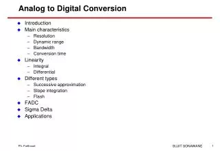
Types of Analog to Digital Converters 1. Counter Type 2. Integrating or Dual Slope 3. Parallel or Flash 4. Successive Approximation
Counter Type START Comparator Vin Control Logic clock Counter D A C Digital Output • When START is received, • control logic initializes the system, (sets counter to 0), and • turns on Clock sending regular pulses to the counter.
As the Clock sends regular pulses to the counter, the counter outputs a digital signal to the Digital-to-Analog converter START Comparator Vin Control Logic clock Counter D A C Digital Output
As the counter counts, its output to the D A C generates a staircase ramp to the comparator. START Comparator Vin Control Logic clock Counter D A C Digital Output
As the ramp voltage increases to the comparator, it rises closer and closer to Vin at which point the comparator shifts states START Comparator Vin Control Logic clock Counter D A C Digital Output
When the ramp voltage exceeds Vin , the comparator output shifts which signals the control logic to turn off the clock Comparator With the clock off, the counter reading is proportional to Vin Vin Note that the conversion time depends on the size of the input signal Vin V’in Conversion time Conv.time
Once the digital output has been read by the associated circuitry, a new start signal is sent, repeating the cycle. START Comparator Vin Control Logic clock Counter D A C Digital Output
With a counter type A/D, if the signal is varying rapidly, the counter must count up and reset before each cycle can begin, making it difficult to follow the signal.
Tracking ADC - similar to the counter type except it uses an up/down counter and can track a varying signal more quickly Comparator Vin Track & Hold Logic clock Up/Down Counter D A C Digital Output
Integrating or Dual Slope A/D integrator comparator Vin -Vref clock Control logic Counter Digital Output
When conversion is initialized, the switch is connected to Vin which is applied to the op amp integrator. The integrator output (>0) is applied to the comparator integrator comparator Vin -Vref clock Control logic Counter Digital Output
As conversion is initiated, the control logic enables the clock which then sends pulses to the counter until the counter fills (9999) integrator comparator Vin -Vref clock Control logic Counter Digital Output
As the counter resets (9999 0000), an overflow signal is sent to the control logic this activates the input switch from Vin to -Vref , applying a negative reference voltage to the integrator integrator comparator Vin -Vref clock Control logic overflow Counter Digital Output
The negative reference voltage removes the charge stored in the integrator until the charge becomes zero. At this point, the comparator switches states producing a signal that disables the clock and freezes the counter reading. The total number of counts on the counter (determined by the time it took the fixed voltage Vref to cancel Vin ) is proportional to the input voltage, and thus is a measure of the unknown input voltage.
The operation of this A/D requires 2 voltage slopes, hence the common name DUAL-SLOPE. full scale conversion charging up the capacitor discharging the capacitor half scale conversion Integrator Output Voltage quarter scale conversion fixed time measured time
Since this A/D integrates the input as part of the measuring process, any random noise present in the signal will tend to integrate to zero, resulting in a reduction in noise. These type of A/D s are used in almost all digital meters. Such meters usually are not used to read rapidly changing values in the lab. Consequently the major disadvantage of such converters (very low speeds) is not a problem when the readout update rate is only a few times per second.
Flash Converters If very high speed conversions are needed, e.g. video conversions, the most commonly used converter is a Flash Converter. While such converters are extremely fast, they are also very costly compared to other types.
Parallel or Flash Converters The resistor network is a precision voltage divider, dividing Vref (8 volts in the sample) into equal voltage increments (1.0 volts here) to one input of the comparator. The other comparator input is the input voltage Each comparator switches immediately when Vin exceeds Vref . Comparators whose input does not exceed Vref do not switch. A decoder circuit (a 74148 8-to-3 priority decoder here) converts the comparator outputs to a useful output (here binary)
The speed of the converter is limited only by the speeds of the comparators and the logic network. Speeds in excess of 20 to 30 MHz are common, and speeds > 100 MHz are available ($$$$$). The cost stems from the circuit complexity since the number of comparators and resistors required increases rapidly. The 3-bit example required 7 converters, 6-bits would require 63, while an 8-bits converter would need 256 comparators and equivalent precision resistors.
While integrating or dual-slope A/Ds are widely used in digital instruments such as DVMs, the most common A/D used in the laboratory environment is the successive approximation. Successive approximation converters are reasonably priced for large bit values, i.e. 10, 12 and even 16 bit converters can be obtained for well under $100. Their conversion times, typically ~ 10-20 s, are adequate for most laboratory functions.
Successive-Approximation A/D Vref analog input D/A Converter Digital Output Data comparator Successive Approximation Register clock STRT At initialization, all bits from the SAR are set to zero, and conversion begins by taking STRT line low.
Successive-Approximation A/D Vref analog input D/A Converter Digital Output Data comparator Successive Approximation Register clock STRT First the logic in the SAR sets the MSB bit equal to 1 (+5 V). Remember that a 1 in bit 7 will be half of full scale.
Successive-Approximation A/D Vref analog input D/A Converter Digital Output Data comparator Successive Approximation Register clock STRT The output of the SAR feeds the D/A converter producing an output compared to the analog input voltage. If the D/A output is < Vin then the MSB is left at 1 and the next bit is then tested.
Successive-Approximation A/D Vref analog input D/A Converter Digital Output Data comparator Successive Approximation Register clock STRT If the D/A output is > Vin then the MSB is set to 0 and the next bit is set equal to 1.
Successive bits are set and tested by comparing the DAC output to the input Vin in an 8 step process (for an 8-bit converter) that results in a valid 8-bit binary output that represents the input voltage.
analog input voltage ¾FS D/A output for 8-bit conversion with output code 1011 0111 ½FS ¼FS CLOCK PERIOD 1 2 3 4 5 6 7 8
Successive approximation search tree for a 4-bit A/D 1111 1110 1101 1100 1011 1010 1001 1000 0111 0110 0101 0100 0011 0010 0001 D/A output compared with Vin to see if larger or smaller
Note that the successive approximation process takes a fixed time - 8 clock cycles for the 8-bit example. For greater accuracy, one must use a higher bit converter, i.e. 10-bit, 12-bit, etc. However, the depth of the search and the time required increases with the bit count.
Workbench Models flash adc(works).ewb dac_dig.ewb adc-dac2.ewb