Analog to Digital Conversion
Analog to Digital Conversion. Based on Chapter 5 of William Stallings, Data and Computer Communication, 8 th Ed. Kevin Bolding Electrical Engineering Seattle Pacific University. Analog to Digital Conversion. Convert a continuous analog signal to a stream of bits for transmission.


Analog to Digital Conversion
E N D
Presentation Transcript
Analog to Digital Conversion Based on Chapter 5 of William Stallings, Data and Computer Communication, 8th Ed. Kevin BoldingElectrical EngineeringSeattle Pacific University
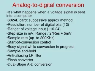
Analog to Digital Conversion • Convert a continuous analog signal to a stream of bits for transmission • Why convert? • Transmission channel uses digital symbols (e.g. line coding) • Storage method is digital (e.g. computer system) • Digital methods have some sort of preferred characteristic • Overview of the process • Sample the analog signal • Quantitize (convert analog samples to discrete) • Send digital data as a stream of bits
Sampling theorem: If sample rate > 2x max frequency (f) And samples have infinite precision (analog) Can reproduce signal exactly after filtering out frequencies >f Sampling • Sampling – Take “snapshots” of analog signal at a regular interval 15 14 13 12 11 10 9 8 7 6 5 4 3 2 1 0 Pulse-Amplitude Modulation – PAM Samples have analog (infinite precision) values • Undersampling • If sample rate is < 2f then it is possible to map multiple waveforms to the data (aliasing)
PCM: Approximate analog samples with a discrete sample n bit sample 2n levels 7 8 10 13 13 12 10 7 2 1 1 1 2 5 7 8 Pulse Code Modulation 15 14 13 12 11 10 9 8 7 6 • Errors • Not analog, so quantizing error is present • Each additional bit halves the quantizing error (in volts) • SNR is Power ratio (proportional to V2) • Each extra bit used increases SNR by factor of 4 (6.02 dB) 5 4 3 2 1 0 For n-bit quantization, the SNR =6.02(n) + 1.76 dB
Linear coding samples using a linear scale Large amplitude Cross many levels during waveform (good) 15 14 13 12 11 10 9 8 7 6 5 4 3 2 1 0 Nonlinear coding 15 14 13 12 11 10 9 8 7 6 5 4 3 • Small amplitude Cross few levels during waveform (bad) 2 1 0 • Nonlinear encoding • More levels concentrated near the center level • Wider spacing at edges
Send info on changes to the signal Standardize to a quantization level Signal increase --> ‘1’ Signal decrease --> ‘0’ 1-bit Delta 2-bit Delta Delta Modulation • May have slope overload • Increase to a multibit delta • 2-bit delta allows +2,+1,-1,-2 • No code for “don’t change” • Flat signals become square waves