Analog to Digital conversion
340 likes | 684 Vues
Analog to Digital conversion. Introduction. The process of converting an analog signal into an equivalent digital signal is known as Analog to Digital (AD) conversion. The conversion time depends upon the frequency of input clock signal. Analog to digital conversion.

Analog to Digital conversion
E N D
Presentation Transcript
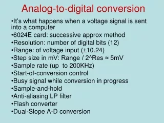
Introduction • The process of converting an analog signal into an equivalent digital signal is known as Analog to Digital (AD) conversion. • The conversion time depends upon the frequency of input clock signal.
Analog to digital conversion 03 07 10 14 09 02 00 04
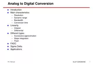
Conversion Methods • Ladder Comparison • Successive Approximation • Slope Integration • Flash Comparison
Slope integration • Charge a capacitor at constant current • Count clock ticks • Stop when the capacitor voltage matches the input • Cannot achieve high resolution • Capacitor and/or comparator Vin Counting time StartConversion StartConversion Enable S Q R N-bit Output C Counter IN Clk Oscillator
Flash comparison • If N is the number of bits in the output word…. • Then 2N comparators will be required. • With modern microelectronics this is quite possible, but will be expensive.
ADC Essentials Basic I/O Relationship • ADC is Rationing System • x = Analog input / Reference • Fraction: 0 ~ 1
ADC Essentials Quantization Error • 1/2 LSB • Reduced by increasing n n bits ADC • Number of discrete output level : 2n • Quantum • LSB size • Q = LSB = FS / 2n
Converter Errors Offset Error Gain Error
Converter Errors Integral Linearity Error Differential Linearity Error
A/D conversion Techniques • Counter or Tracking ADC • Successive Approximation ADC • Most Commonly Used • Dual Slop Integrating ADC • Voltage to Frequency ADC • Parallel or Flash ADC • Fast Conversion • Software Implementation • Shaft Encoder
Counter type ADC Block Diagram Wave form
Counter type ADC Operation • Reset and Start Counter • DAC convert Digital output of Counter to Analog signal • Compare Analog input and Output of DAC • Vi < VDAC • Continue counting • Vi = VDAC • Stop counting • Digital Output = Output of Counter
Tracking type ADC Tracking or servo type • Using Up/Down Counter to track input signal continuously • For slow varying input
Successive Approximation ADC Block Diagram • Most Commonly used in medium to high speed Converters • Based on approximating the input signal with binary code and then successively revising this approximation until best approximation is achieved • SAR(Successive Approximation Register) holds the current binary value
Successive Approximation ADC Circuit wave form Logic Flow
Dual slope integrating ADC Operation • Integrate • Reset and integrate • Thus •
Dual slope integrating ADC Low speed • If T1 = 60Hz, converter throughput rate < 30 samples/s Excellent Noise Rejection • High frequency noise cancelled out by integration • Proper T1 eliminates line noise • Easy to obtain good resolution
Voltage to Frequency ADC VFC (Voltage to Frequency Converter) • Convert analog input voltage to train of pulses Counter • Generates Digital output by counting pulses over a fixed interval of time
Voltage to Frequency ADC • Low speed • Good noise immunity • High resolution • For slow varying signal • With long conversion time • Applicable to remote data sensing in noisy environments • Digital transmission over a long distance
Parallel or Flash ADC Single step Conversion • 2n –1 comparator • Precision Resistive Network • Encoder Very high speed conversion • Up to 100MHz for 8 bit resolution • Video, Radar, Digital Oscilloscope Resolution is limited • Large number of comparator in IC
Software Implementation Implementing software using Microprocessor • Counting • Shifting • Inverting • Code conversion • ….. Limited practical use • Availability if Good performance with very responsible cost
Shaft Encoder Electromechanical ADC • Convert shaft angle to digital output Encoding • Optical or magnetic sensor Applications • Machine tools, industrial robotics, Numerical control
Shaft Encoder Binary Encoder • Misalignment of mechanism causes large error. Ex: 011 -> 111 (180 deg) Gray Encoder • Misalignment causes of 1 LSB error.
The End ……. Thank You ……