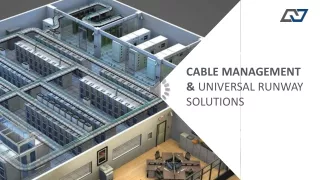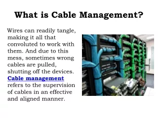
Cable Design and Management
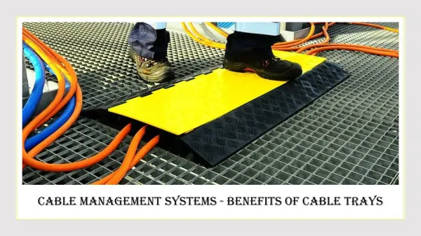
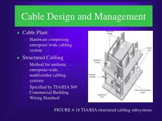
Cable Design and Management. Cable Plant Hardware comprising enterprise-wide cabling system Structured Cabling Method for uniform, enterprise-wide, multivendor cabling systems Specified by TIA/EIA 569 Commercial Building Wiring Standard. FIGURE 4-18 TIA/EIA structured cabling subsystems.

Cable Design and Management
E N D
Presentation Transcript
Cable Design and Management • Cable Plant • Hardware comprising enterprise-wide cabling system • Structured Cabling • Method for uniform, enterprise-wide, multivendor cabling systems • Specified by TIA/EIA 569 Commercial Building Wiring Standard FIGURE 4-18 TIA/EIA structured cabling subsystems
Cable Design and Management • Entrance facilities • Backbone wiring • Backbone is essentially a network of networks • Risers provide vertical connections between floors TABLE 4-2 TIA/EIA specifications for backbone cabling
Cable Design and Management • Equipment room • Telecommunications closet • Punch-down block is a panel of data receptors • Patch panel is a wall-mounted panel of data receptors FIGURE 4-19 Patch panel (left) and Punch-down block (right)
Cable Design and Management • Horizontal wiring FIGURE 4-20 Horizontal wiring
Cable Design and Management • Work area • Patch cable is a relatively short section of twisted-pair cabling with connectors on both ends that connect network devices to data outlets Figure 4-22 Standard TIA/EIA wall jack
Cable Design and Management FIGURE 4-22 Structured cabling hierarchy
Installing Cable FIGURE 4-23 Typical UTP cabling installation
Installing Cable TABLE 4-3 Pin numbers and color codes for an RJ-45 connector
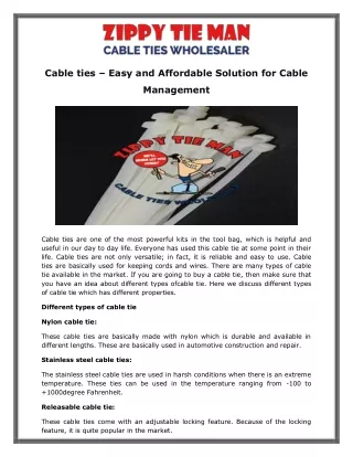
Installing Cable • Do not untwist twisted-pair cables more than one-half inch before inserting them • Do not strip off more than 1 inch of insulation from copper wire in twisted-pair cables • Watch bend radius limitations for cable being installed • Bend radius is maximum arc into which a cable can be looped before its data transmission is impaired • Test each segment of cabling with cable tester • Use only cable ties to cinch groups of cable together
Installing Cable • Avoid laying cable across floor where it may sustain damage • Install cable at least 3 feet away from fluorescent lights or other sources of EMI • Always leave slack in cable runs • If running cable in the plenum, the area above ceiling tile or below subflooring, make sure cable sheath is plenum-rated • Pay attention to grounding requirements
Atmospheric Transmission Media • Infrared Transmission • Infrared networks use infrared light signals to transmit data • Direct infrared transmission depends on transmitter and receiver remaining within line of sight • In indirect infrared transmission, signals can bounce off of walls, ceilings, and any other objects in their path
Atmospheric Transmission Media • RF Transmission • Radio frequency (RF) transmission relies on signals broadcast over specific frequencies • Narrowband concentrates significant RF energy at a single frequency • Spread spectrum uses lower-level signals distributed over several frequencies simultaneously
Choosing the Right Transmission Media • Areas of high EMI or RFI • Corners and small spaces • Distance • Security • Existing infrastructure • Growth
Chapter Summary • Information can be transmitted via analog or digitally • Both signals suffer attenuation • Throughput is the amount of data a medium can transmit during a given period of time • Costs depend on many factors • Three specifications dictating networking media • Length of a network segment is limited due to attenuation
Chapter Summary • Connectors connect wire to the network device • Coaxial cable consists of central copper core surrounded by an insulator and a sheath • In baseband transmission, digital signals are sent through direct current pulse applied to the wire • Thicknet cabling is a rigid coaxial cable used for original Ethernet networks • Thinnet was popular for Ethernet LANs in the 1980s • Both Thicknet and Thinnet rely on bus topology and must be terminated at both ends
Chapter Summary • Twisted-pair cable consists of color-coded pairs of insulated copper wires, twisted around each other and encased in plastic coating • The more twists per inch in a pair of wires, the more resistant to noise • STP cable consists of twisted pair wires individually insulated and surrounded by a shielding • UTP cabling consists of one or more insulated wire pairs encased in a plastic sheath • UTP comes in a variety of specifications
Chapter Summary • Maximum segment length for both STP and UTP is 100m • Fiber-optic cable contains one or several glass fibers in its core • Fiber cable variations fall into two categories • On today’s networks, fiber is used primarily as backbone cable • In 1991, TIA/EIA released their joint 568 Commercial Building Wire Standard
Chapter Summary • Best practice for installing cable is to follow the TIA/EIA 568 specifications and manufacturer’s recommendations • Wireless LANs can use radio frequency (RF) or infrared transmission • Infrared transmission can be indirect or direct • RF transmission can be narrowband or spread spectrum • To make correct media transmission choices, consider, throughput, cabling, noise resistance, security/flexibility, and plans for growth