Download
1 / 40
450 likes | 857 Vues
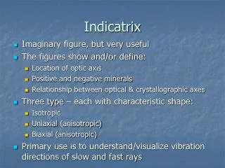
GLG212 Part II, Lecture 1: Indicatrix and interference figures. Objectives. Understand principles of: Birefringence (continued) Optical indicatrix Interference figures. The Optical Indicatrix.

E N D
GLG212Part II, Lecture 1:Indicatrix and interference figures
Objectives • Understand principles of: • Birefringence (continued) • Optical indicatrix • Interference figures
The Optical Indicatrix • If we construct vectors whose direction corresponds to the vibration direction, and whose length corresponds to the refractive index of the material for light with that vibration direction, their tips will define an imaginary surface called the indicatrix.
The Optical Indicatrix The indicatrix is a shape called an ellipsoid. Every cross section of an ellipsoid is an ellipse. The longest direction of the ellipsoid is its major axis. The shortest direction, perpendicular to the major axis, is called the minor axis. Perpendicular to the major and minor axes is the intermediate axis. These three axes are called the principal axes.
The Optical Indicatrix • A geometric figure that shows the index of refraction and vibration direction for light passing in any direction through a material is called an optical indicatrix. • n = refractive index • The indicatrix is constructed by plotting indices of refraction as radii parallel to the vibration direction of the light. • Ray p, propagating along Y, vibrates parallel to the Z-axis so its index of refraction (np) is plotted as radii along Z. • Ray q, propagating along X, vibrates parallel to Y so its index of refraction (nq) is plotted as radii along Y. • If the indices of refraction for all possible light rays are plotted in a similar way, the surface of the indicatrix is defined. The shape of the indicatrix depends on mineral symmetry.
Isotropic Indicatrix • Optically isotropic minerals all crystallize in the isometric crystal system. • One unit cell dimension (a) is required to describe the unit cell and one index of refraction (n) is required to describe the optical properties because light velocity is uniform in all directions for a particular wavelength of light. • The indicatrix is therefore a sphere. • All sections through the indicatrix are circles and the light is not split into two rays. • Birefringence may be considered to be zero.
UniaxialIndicatrix • Minerals that crystallize in the tetragonal, trigonal and hexagonal crystal systems have two different unit cell dimensions (a and c) and a high degree of symmetry about the c axis. • Two indices of refraction are required to define the dimensions of the indicatrix, which is an ellipsoid of revolution whose axis is the c crystal axis. • The semiaxis of the indicatrix measured parallel to the c axis is called ne, and the radius at right angles is called nw. The maximum birefringence of uniaxial minerals is always [ne - nw]. • All vertical sections through the indicatrix that include the c axis are identical ellipses called principal sections whose axes are nw and ne. Random sections are ellipses whose dimensions are nw and ne’ where ne’ is between nw and ne. • The section at right angles to the c axis is a circular section whose radius is nw. Because this section is a circle, light propagating along the c axis is not doubly refracted as it is following an optic axis. • Because hexagonal and tetragonal minerals have a single optic axis, they are called optically uniaxial.
Uniaxial Indicatrix - Positive • Z (longest) axis = optic axis = c
Uniaxial Indicatrix - Negative • X (shortest) axis = optic axis = c-axis
Use of the Indicatrix • In this example the mineral is oriented so that its optic axis is horizontal • We will assume that the mineral is uniaxial positive • The wave normal is through the centre of the indicatrix and light is incident normal to the bottom surface of the grain. • Because the optic axis is horizontal, this section is a principal section, which is an ellipse whose axes are nw and ne. • Therefore • Ordinary ray = nw • Extraordinary = ne • Maximum because the mineral is optically positive. • The extraordinary ray vibrates parallel to the trace of the optic axis (c axis) and the ordinary ray vibrates at right angles. • Therefore, birefringence and hence interference colors are maximum values.
Use of the Indicatrix • In this case the mineral sample is oriented so that the optic axis is vertical. • The section through the indicatrix perpendicular to the wave normal is the circular section whose radius is nw. • Light coming from below is not doubly refracted, birefringence is zero and the light preserves whatever vibration direction it initially had. • Between crossed polars this mineral should behave like an isotropic mineral and remain dark as the stage is rotated. • However, because the light from the substage condenser is moderately converging, some light may pass through the mineral. • The mineral may display interference colors but they will be the lowest order found in that mineral.
Use of the Indicatrix • In this sample the mineral sample is oriented in a random orientation so that the light path is at an angle q to the optic axis. • The section through the indicatrix parallel to the bottom surface of the mineral is an ellipse whose axes are nw and ne • The extraordinary ray vibrates parallel to the trace of the optic axis as seen from above, while the ordinary ray vibrates at right angles • Both birefringence and interference colors are intermediate because ne’ is intermediate between nw and ne.
Biaxial Indicatrix • Minerals that crystallize in the orthorhombic, monoclinic and triclinic crystal systems require three dimensions (a, b and c) to describe their unit cells and three indices of refraction to define the shape of their indicatrix • The three principal indices of refraction are na, nb and ng where na < nb < ng. • The maximum birefringence of a biaxial mineral is always ng - na • Construction of a biaxial indicatrix requires that three indices of refraction are plotted • However, while three indices of refraction are required to describe biaxial optics, light that enters biaxial minerals is still split into two rays. • As we shall see, both of these rays behave as extraordinary rays for most propagation paths through the mineral • The index of refraction of the fast ray is identified as na’ where na < na’ < nb and the index of refraction of the slow ray is ng’ where nb < ng’ < ng
Biaxial Indicatrix • The biaxial indicatrix contains three principal sections, the YZ, XY and XZ planes. • The XY section is an ellipse with axes na and nb, • The XZ section is an ellipse with axes na and ng • YZ section is an ellipse with axes nb and ng. • Random sections through the indicatrix are ellipses whose axes are na’ and ng’. • The indicatrix has two circular sections with radius nb that intersect the Y axis. • The XZ plane is an ellipse whose radii vary between na and ng. Therefore radii of nb must be present. • Radii shorter than nb are na’ and those that are longer are ng’. • The radius of the indicatrix along the Y axis is also nb
Biaxial Indicatrix An ellipse with three unequal principal axes has two circular cross sections. The plane containing the major and minor axis cuts the ellipsoid in an ellipse with the maximum and minimum possible radii. Somewhere in between is a radius equal to the intermediate axis. The two circular sections have radius equal to the intermediate axis and intersect along the intermediate axis. They are shown in blue and purple at left.
Biaxial Indicatrix • The directions perpendicular to each one of the circular sections are the optic axes. • For a generic ellipsoid with three unequal axes, there are two optic axes. Such materials are called biaxial.
Biaxial Indicatrix – XZ plane • Therefore the Y axis and the nb radii in the XZ plane define the two circular sections. • Like uniaxial minerals, the circular sections in biaxial minerals are perpendicular to the optic axes, hence the term biaxial. • Because both optic axes lie in the XZ plane of the indicatrix, that plane is called the optic plane. • The angle between the optic axes bisected by the X axis is also called the 2Vx angle, while the angle between the optic axes bisected by the Z axis is called the 2Vz angle where 2Vx + 2Vz = 180°. • The Y axis, which is perpendicular to the optic plane is called the optic normal.
Optic Sign – Biaxial Minerals • The acute angle between the optic axes is called the optic angle or 2V angle. • The axis (either X and Z)that bisects the acute angle between the optic axes is the acute bisectrix or Bxa. • The axis (either Z or X) that bisects the obtuse angle between the optic axes is the obtuse bisectrix or Bxo. • The optic sign of biaxial minerals depends on whether the X or Z indicatrix axis bisects the acute angle between the optic axes. • If the acute bisectrix is the X axis, the mineral is optically negative and 2Vx is less than 90° • If the acute bisectrix is the Z axis, the mineral is optically positive and 2Vz is less than 90° • If 2V is exactly 90° so neither X nor Z is the acute bisectrix, the mineral is optically neutral.
Indicatrix Axes and Orthorhombic Crystals • Orthorhombic crystals have three mutually perpendicular crystallographic aces of unequal length. These crystal axes must coincide with the three indicatrix axes and the symmetry planes in the mineral must coincide with principal sections in the indicatrix. Any crystal axis may coincide with any indicatrix axis however. • The optic orientation is defined by indicating which indicatrix axis is parallel to which mineral axis. • Aragonite X = c, Y = a, Z = b • Anthophyllite X = a, Y = b, Z = c
Use of the Biaxial Indicatrix • The biaxial indicatrix is used in the same way as the uniaxialindicatrix. • It provides information about the indices of refraction and vibration direction given the wave normal direction that light is following through a mineral. • Birefringence depends on how the sample is cut or mounted. • Birefringence is: • A maximum if the optic plane is horizontal • A minimum if an optic axis is vertical • Intermediate for all other random orientations
Birefringence (continued) • Birefringence: the double refraction of light in a transparent, molecularly ordered material, which is manifested by the existence of orientation dependent differences in refractive index • Calculated as: • Birefringence (B) = |ne - no|, with e – extraordinary ray; O – ordinary ray • This is the birefringence that a specific ray of light experience through a specific direction of a crystal • Minerals has specific values of birefringence (measure how high is the degree of birefringence that can be caused by that mineral) • The maximum possible birefringence (also called the retardation) that can be caused a specific mineral is calculated as follows, (t = the thickness of the mineral, thus the thickness of the thin section): • Isotropic: Δn = t.|na - na| = 0 • Anisotropic uniaxial: Δn = t.|nω - nε| • Anisotropic biaxial: Δn = t.|nγ - nα|
Interference colours First order colors Second order colors Third order colors
Birefringence • A characteristic that all anisotropic minerals have, intensity differs • High birefringent minerals – third/fourth order interference colours • Med birefringent minerals – second order interference colours • Low birefringent minerals - first order interference colours • For specific mineral birefringence depends on orientation: • Maximum birefringence - orientation of grain shows highest possible interference colour for the specific mineral • Minimum or no birefringence – orientation of grain shows lowest or no interference colour for specific mineral • Intermediate birefringence – orientation of grains shows interference colours intermediate between minimum and maximum
Observation of interference figures using convergent light – conoscopic view • Insert condenser lens • Gives convergent light • Enters sample at 50º - 90º angles • See image of light source • Interference effects at different angles
Conoscopic observation of interference figures • Isotropic • No image
Conoscopic observation of interference figures • Uniaxial • Perpendicular to optical axis
Conoscopic observation of interference figures • Uniaxial • At an angle to the optical axis
Conoscopic observation of interference figures • Uniaxial • Parallel to the optical axis
Conoscopic observation of interference figures • Biaxial • Perpendicular to acute bisectrix • 2V angle < 60°
Conoscopic observation of interference figures • Biaxial • Perpendicular to acute bisectrix • 2V angle > 60° (but still < 90 °)
Conoscopic observation of interference figures • Biaxial • Perpendicular to optical axis • 2V < 30°
Conoscopic observation of interference figures • Biaxial • Perpendicular to optical axis • 2V > 30° (but still < 90 °)
Conoscopic observation of interference figures • Biaxial • Perpendicular to obtuse bisectrix
Conoscopic observation of interference figures • Biaxial • Parallel to the axial plane
Conoscopic observation of interference figures • Biaxial • Off-centre interference figures
Conoscopic observation of interference figures • Biaxial • Off-centre interference figures