Local Area Networks and Medium Access Control Protocols
400 likes | 443 Vues
Explore how Local Area Networks facilitate direct communication among devices in a limited area and learn about MAC protocols for data transmission efficiency.

Local Area Networks and Medium Access Control Protocols
E N D
Presentation Transcript
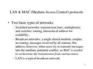
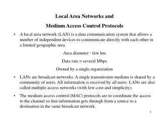
Local Area Networks and • Medium Access Control Protocols • A local area network (LAN) is a data communication system that allows a number of independent devices to communicate directly with each other in a limited geographic area. • Area diameter · few km • Data rate = several Mbps • Owned by a single organization • LANs are broadcast networks. A single transmission medium is shared by a community of users. All information is received by all users. LANs are also called multiple access networks (with low-cost and simplicity). • The medium access control (MAC) protocols are to coordinate the access to the channel so that information gets through from a source to a destination in the same broadcast network.
In 1985, the Computer Society of the IEEE started a project, called Project 802, to set up standards so that LAN equipments manufactured by different companies is compatible. • Project 802 divides the data link layer into sub-layers: • Logical link control (LLC) • Media access Control • LAN compared with the OSI model
The LLC is the upper sublayer and is same for all LANs. Its functions include error detection and retransmission. • The MAC sublayer coordinates the data link tasks within a specific LAN. • The MAC sublayer is manufacturer-specific and dependent on the LAN type. • For LANs specified by project 802 are following: • Ethernet (802.3) • Token bus (802.4) • Token ring (802.5) • Wireless LANs (802.11)
Sharing a transmission medium • Static sharing (channelization schemes) is a collision-free sharing • Dynamic sharing (MAC schemes) minimizes the incidence of collision • Random access methods constitute the first major class of MAC procedures
ALOHA random access scheme • It was developed at the University of Hawaii in the early 1970s to connect computers situated on different Hawaiian islands. The computers of the ALOHA network transmit on the same radio channel whenever they have a packet to transmit. From time-to-time packet transmission will collide, but these can be treated as transmission errors, and recovery can take place by retransmission. When traffic is very light, the probability of collision is very small, and so retransmissions need to be carried out infrequently. • ALOHA scheme requires stations to use a random retransmission time. (This randomization is intended to spread out the retransmission and reduces the likelihood of additional collisions between stations. ) • ALOHA is the father of multiple access protocols.
First transmission Retransmission Backoff period B t t0 t0+X t0-X t0+X+2tprop + B t0+X+2tprop Time-out • Pure ALOHA (unslotted ALOHA): • Protocol • A user transmits whenever it has packets to transmit • When two or more packet transmissions overlap in time, a collision occurs and all the packets involved in the collision are destroyed. (non-capture) • If ACK not received within timeout, then a user picks random backoff time (to avoid repeated collision) • User retransmits packet after backoff time
Analysis (Throughput and delay) • Definitions and assumptions • X: packet transmission time (assume constant) • S: throughput (average # successful packet transmissions per X seconds) • G: load (average # transmission attempts per X sec) • Traffic traffic (new arrivals + retransmissions) is a Poisson process with rate G packet/slot • The probability of a successful transmission is the probability that they are no additional packet transmission in the vulnerable period.
Throughput S versus load G for pure ALOHA S reaches a peak value of 1/2e at G=0.5, and then declines back toward 0. For a given value of S, say, S=0.05, there are two associated values of G. For small G, S ¼ G. For large G, there are many backlogged users. ALOHA system cannot achieve throughput higher than 18.4 percent (1/2e).
The average (delay) number of transmission attempts/packet is G/S=e2G attempts per packet The avergae number of unsuccessful attempts per packet is =G/S-1=e2G-1 The first transmission requires X+tprop seconds, and each subsequent retransmission requires 2tprop+X+B, where B is the average backoff time and tprop is the one way propagation delay. Thus the average packet transmission time is approximately given by E[Taloha]=X+tprop+(e2G-1)(X+2tprop+B) Express delay in multiples of X E[Taloha]/X=1+a+(e2G-1)(1+2a+B/X) Where a=tprop/X is the one way normalized propagation delay. If the backoff time is uniformly distributed between 1 and K packet transmission times, then B=(K+1)X/2
ALOHA network ALOHA is a packet-switched radio communication network that was invented by Norm Abrahmson at the University of Hawaii in the early 1970s. Ethernet is its direct descendant.
Backoff period B t (k+1)X t0+X+2tprop kX t0+X+2tprop+ B Time-out Vulnerableperiod Slotted ALOHA Slotted ALOHA is to constrain the user to transmit in synchronized fashion. All users keep track of transmission slots and are allowed to initiate transmission only at the beginning of a time slot (the time axis is divided into time slots with durations equal to the time to transmit a packet) Only packets that arrive during prior X seconds collide.
0.368 Ge-G S 0.184 Ge-2G G Throughput of Slotted ALOHA
Smax=1/e=36.8% Efficiency=throughput · 36% (upper bound=36%) The average packet delay in slotted ALOHA E[Tslotted-aloha]/X=1+a+(eG-1)(1+2a+B/X) Example – ALOHA and Slotted ALOHA Suppose that a radio system uses a 9600 bps channels for sending call setup request messages to a base station. Suppose that packets are 120 bits long, that the timeout is 20ms, and that the backoff is uniformly distributed between 1 and 7. What is the maximum throughput possible with ALOHA and slotted ALOHA? Compare the average delay in ALOHA and slotted ALOHA when the load when the load is 40 percent of the maximum possible throughput of the ALOHA system.
The system transmits packets at a rate of 9600 bits/second£1 packet/120bits = 80 packets/second. The maximum throughput for ALOHA is then 80(0.184) ¼ 15 packets/second. The maximum throughput for slotted ALOHA is then ¼ 30 packets/second. The load at 40 percent of the maximum of the ALOHA system is 15 £ 0.40 = 6 packets/second. G is expressed in packet arrivals/packet transmission time, therefore, G=6/80. Assuming that the propagation delay is negligible, the average packet delay for ALOHA in multiples of X is then 1+(e12/80-1)(1+(1+7)/2)=1.81 packet transmission time. The slotted ALOHA system with a load of 6 packets/second 1+(e6/80-1)(1+(1+7)/2)=1.39 packet transmission time.
Application of Slotted ALOHA cycle • Reservation protocol allows a large number of stations with infrequent traffic to reserve slots to transmit their packets in future cycles • Each cycle has mini-slots allocated for making reservations • Stations use slotted ALOHA during mini-slots to request slots . . . . . . Reservation mini-slots X-second slot
Carrier Sense Multiple Access with Collision Detection The access mechanism used in an Ethernet is called CSMA/CD, standardized in IEEE 802.3 CSMA/CD is the result of an evolution from multiple access (MA) to carrier sense multiple access (CSMA), and finally, to CSMA/CD. In MA, there was no provision for traffic coordination. In a CSMA system, any user (work station) wishing to transmit must first listen to the existing traffic on the line. A device listens by checking for a voltage. No voltage means the line is idle. CSMA cuts down on the number of collisions but does not eliminate them. In CSMA/CD system, the station listens again after each packet transmission. The extremely high voltages indicate a collision.
Station A begins transmission at t = 0 A Station A captures channel at t = tprop A Carrier Sensing Multiple Access (CSMA) • A station senses the channel before it starts transmission • If busy, either wait or schedule backoff (different options) • If idle, start transmission • Vulnerable period is reduced to tprop(due to channel capture effect) • When collisions occur they involve entire frame transmission times • If tprop >X (or if a>1), no gain compared to ALOHA or slotted ALOHA BS (another station)
Sensing CSMA Options • Transmitter behavior when busy channel is sensed • 1-persistent CSMA (most greedy) • Start transmission as soon as the channel becomes idle • Low delay and low efficiency • Non-persistent CSMA (least greedy) • Wait a backoff period, then sense carrier again • High delay and high efficiency • p-persistent CSMA (adjustable greedy) • Wait till channel becomes idle, transmit with prob. p; or wait one tprop time & re-sense with probability 1-p • Delay and efficiency can be balanced (spread out the transmission attempts)
Throughput versus load G for 1-persistent (three different a=tprop/X ) S An analysis of the throughput S versus load G for CSMA is beyond the scope of this text. 0.53 1-Persistent CSMA 0.01 0.45 0.16 0.1 G 1 The normalized propagation delay a = tprop/X has a significant impact on the maximum achievable throughput since tprop constitutes the vulnerable period. Figure 6.21 - Part 2
Throughput versus load G for non-persistent (three different a=tprop/X ) S 0.81 Non-Persistent CSMA 0.01 0.51 0.14 0.1 G 1 1-persistent is sharper than non-persistent. a=tprop/X has import impact on the throughput. When a approaches 1, both 1-persistent and non-persistent is worse than ALOHAs. Figure 6.21 - Part 1
Analysis of CSMA/CD protocol • In CSMA/CD protocol, a node with a packet to transmit must proceed as follows: • Wait until the channel is idle; • When the channel is idle, transmit and listen while transmitting • In case of a collision, stop the packet transmission, and then wait for a random delay and go to (1). • Note: when a node “goes back to (1)” after its waiting time, it senses the signal from the other nodes and must then wait until the end of that transmission before transmitting. • In CSMA, collisions result in wastage of X seconds spent transmitting an entire frame • CSMA-CD reduces wastage of time (or bandwidth) to detect collision and abort transmission
A begins to transmit at t = 0 A B B begins to transmit at t = tprop- ; B detects collision at t = tprop B A A detects collision at t= 2 tprop- A B CSMA/CD reaction time It takes 2 tpropto find out if channel has been captured (The reaction time in CSMA-CD is 2tprop)
Efficiency (throughput): The nodes attempt to transmit at discrete times, in time slots with a duration of 2tpropeach. The slot duration of 2tprop is used to guarantee that, if nodes select to transmit at the beginning of two different slots, then they can’t collide. Let be the probability that during a given time slot there is no collision and that one node starts transmitting. Let N (N ¸ 2) nodes compete for a time-slotted channel by transmitting packets with probability p, independently of one another, in any given time slot.
Let A be the average number of time slots that are wasted before a successful transmission A=0 + (1-)(1+A) First time slot is successful First time slot is wasted ) A=-1-1 With =0.4 ) A=1.5 slots where is the time to transmit a packet.
For small a: CSMA-CD has best throughput For larger a: Aloha & slotted Aloha better throughput CSMA/CD 1-P CSMA Non-P CSMA max Slotted ALOHA ALOHA a Throughput for Random Access MACs (throughput)
Tree Protocol for Collision Resolution (divide-and-conquer approach) There are 8 users in a radio cell. At a given epoch, users 0, 1, 2, 5, and 7 have packets ready for transmission, while users 3, 4, and 6 are idle. When the ready users transmit simultaneously, collisions will occur. The interval of time within which the collisions are resolved is referred to as the collision resolution interval (CRI).
Collision resolution can be performed on a per collision resolution interval basis. The channel states are described by the 3-tuple {idle, collision, success}. Assume that the users can detect the channel states. With 8 users, the binary tree has 4 levels, with the root at level 0 and the leaves at level 3, where ready users are indicated by the underline. Level 0 Level 1 Level 2 Level 3
Consider that, at the end of the (i-1)th collision resolution interval, and hence the start of the ith collision resolution interval, users 0, 1, 2, 5 and 7 are ready for packet transmission. At the root node A, collisions occur. Split the tree into two halves and resolve the left half first. Then at intermediate node B (level 1), users 0, 1, and 2 transmit, resulting in collision. Divide the subtree into two halves and search the left half. Users 0 and 1 transmit and collision occurs. Further divide the subtree with node D as the root, into two halves. Since each of the halves only has the leaf node, transmission by user 0, and then by user 1, will both be successful. This completes the search of the left half of the subtree with node D as the root. The algorithm next searchs the right half of the subtree with node B as the root. The procedure is repeated with the entire tree has been searched and all ready users have successfully transmitted.
Scheduling approaches to MAC • About random access: • Simple and easy to implement • In low-traffic, packet transfer has low-delay • However, limited throughput and in heavier traffic, packet delay has no bound. A station of bad luck may never have a chance to transfer its packet. • Scheduling approach: • provides orderly access to shared medium so that every station has chance to transfer
Scheduling approach—reservation protocol • The time line has two kinds of periods: • Reservation interval of fixed time length • Data transmission period of variable frames. • Suppose there are M stations, then the reservation interval has M minislots, and each station has one minislot. • Whenever a station wants to transfer a frame, it waits for reservation interval and broadcasts reservation bit in its minislot.
Scheduling approach—reservation protocol (Cont.) • By listening to the reservation interval, every station knows which stations will transfer frames, and in which order. • The stations having reserved for their frame transfer their frames in that order • After data transmission period, next reservation interval begins.
Reservation protocol Frames-transmission Reservation interval 0 1 2 3 4 5 6 7 0 1 2 3 4 5 6 7 1 1 1 1 3 5 1 1 3 7
Scheduling approach—polling protocol • Stations take turns accessing the medium: • At any time, only one station has access right to transfer into medium • After this station has done its transmission, the access right is handed over (by some mechanism) to the next station. • If the next station has frame to transfer, it transfers the frame, otherwise, the access right is handed over to the next next station. • After all stations are polled, next round polling from the station 1 begins.
Centralized polling vs. distributed polling • Centralized polling: a center host which polls the stations one by one • Distributed polling: station 1 will have the access right first, then station 1 passes the access right to the next station, which will passes the access right to the next next station, …
Interaction of polling messages and transmissions in polling systems polling messages … 2 1 4 5 3 M 1 2 t packet transmissions Figure 6.28
Station interfaces: are connected to form a ring by point-to-point lines Stations: are attached to the ring by station interfaces. token Note: point-to-point lines, not a shared bus. Token: a small frame, runs around the ring, whichever gets the token, it has the right to transmit data frames. The information flows in one direction. Station interfaces have important functions. Token-passing rings – a distributed polling network Figure 6.30
Comparison of scheduling & random access • Scheduling • Methodical orderly access: dynamic form of time division multiplexing, round-robin (only) when the stations have information to send. • Less variability in delay, supporting applications with stringent delay requirement. In high load, performance is good. E.g., token-ring may reach nearly 100 percent of performance when all stations have plenty of information to send. • Some channel bandwidth carries explicit scheduling information.
Comparison of scheduling & random access (Cont.) • Random access • Chaotic, unordered access • If rich bandwidth and light load, random access has low delay, otherwise, delay is undeterminably large. • Quite a lot bandwidth is used in collision to alert stations of the presence of other transmissions.