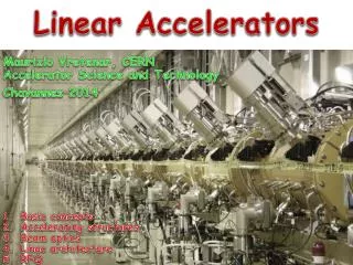
Accelerator Science and Techology
This work presents a collaborative effort among various institutions, including the University of Liverpool and CERN, in the development of a polarized positron source for the International Linear Collider (ILC). The project focuses on utilizing a helical undulator and optimizing capture optics to achieve the required luminosity of approximately 10^14 positrons per second. Key innovations include the design of superconducting undulators, target stations, and photon collimators to enhance performance while minimizing operational stresses. The R&D activities cover simulation, prototype testing, and the overall system design for effective positron production.


Accelerator Science and Techology
E N D
Presentation Transcript
Helical Collaboration I.R. Bailey, J.B. Dainton, L.J. Jenner, L.I. Malysheva (University of Liverpool / Cockcroft Institute) D.P. Barber (DESY / Cockcroft Institute) G.A. Moortgat-Pick (IPPP, University of Durham / CERN / Cockcroft Institute) A. Birch, J.A. Clarke, O.B. Malyshev, D.J. Scott (CCLRC ASTeC Daresbury Laboratory / Cockcroft Institute) E. Baynham, T. Bradshaw, A. Brummit, S. Carr, Y. Ivanyushenkov, J. Rochford (CCLRC Rutherford Appleton Laboratory) P. Cooke (University of Liverpool) http://www.astec.ac.uk/id_mag/ID-Mag_Helical.htm Accelerator Science and Techology Leo Jenner University of Liverpool / Cockcroft Institute
ILC Positron Source & Spin Tracking Ian Bailey University of Liverpool / Cockcroft Institute EUROTeV: WP4 (polarised positron source) PTCD task I. Bailey, J. Dainton, L. Zang (Cockcroft Institute / University of Liverpool) D. Clarke, N. Krumpa, J. Strachan (CCLRC Daresbury Laboratory) C. Densham, M. Woodward, B. Smith, (CCLRC Rutherford Appleton Laboratory) J.L. Fernandez-Hernando, D.J. Scott (CCLRC ASTeC Daresbury Laboratory / Cockcroft Institute) P. Cooke, P. Sutcliffe (University of Liverpool) In collaboration with Jeff Gronberg, David Mayhall, Tom Piggott, Werner Stein (LLNL) Vinod Bharadwaj, John Sheppard (SLAC)
Daresbury Labs Cockcroft Institute: Liverpool, Manchester, Lancaster, AsTeC
Most recent ILC layout… • e+ e- linear collider • Centrally located, stacked damping rings • Single IR with push/pull detector
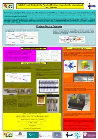
Photons(≈ 10 MeV ) Helical Undulator (≈ 100 m) Electrons (150 GeV) Polarised Positrons (≈ 5 MeV) Conversion Target (0.4X0 Ti) Photon Collimator Undulator-Based Polarised Positron Source for ILC • The ILC requires of order 1014 positrons / s to meet its luminosity requirements. • A factor ~60 greater than the ‘conventional’ SLC positron source. • Undulator based source lower stresses in the production target(s) and less activation of the target station(s). • Collimating the circularly-polarised SR from the undulator leads to production of longitudinally-polarised positrons.
ILC Positron Source Layout Original baseline layout of ILC with undulator at 150GeV position in main linac.
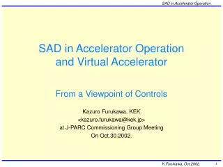
Baseline Positron Source R&D Area Systems Group R&D topics • Undulator - CI • Topic Leader: Jim Clarke • Target station - CI • Topic Leader: Ian Bailey / Tom Piggott • OMD (capture optics) – CI • Target hall (eg layout, remote-handling) - CI • Capture rf cavity • Accelerator physics (eg production/ capture) - CI • Topic Leader: Gudi Moortgat-Pick • Polarisation (collimators, spin transport) - CI Collaborating Institutes DL RAL Cornell SLAC LLNL ANL DESY BINP CI - denotes a significant Cockcroft Institute contribution
Superconducting undulator prototypes for ILC Parameters of first prototype Superconducting bifilar helix First (20 period) prototype Hall probe measurements of first prototype Cut-away showing winding geometry
Superconducting undulator prototypes for ILC Superconducting bifilar helix First (20 period) prototype Section of second prototype, showing NbTi wires in Al former.
Prototype Parameters All completed prototypes have reached design field Peak field specification of < +/- 1% demonstrated Demonstrated predicted enhancement of field by ~0.44T using iron former
ILC Undulator Simulations Undulator simulations showing winding bore and period of device needed for ILC parameters. Simulations of photon desorption of absorbed gases from undulator beam pipe. Collimation required to maintain vacuum of 10-8 Torr. Energy spread increase in ILC electron beam due to resistive wall impedance in undulator vacuum vessel. Red is room temperature, blue is at 77K
He bath vessel Thermal shield Two sections of the undulator magnet Long Prototype Long prototype (4m) now under detailed design and will be manufactured by Summer ‘07. Turret region Cryostat wall – Thermal shield - He vessel - Magnet connection
Future Undulator Activities • Finalise design and construct long undulator prototype (4m) • Prototype beam tests • ERLP at Daresbury Laboratory • 70 MeV electron beam visible light emitted • Pre-production prototype • Construct with UK industry • Module alignment issues • Module instrumentation • Collimation • Integrated vacuum system • Extend simulations • e.g. Geometric Wakefields
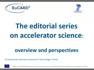
Target Systems The CI plays a key role in the EUROTeV-funded task to carry out design studies of the conversion target and photon collimator for the polarised positron source. Capture Optics Positron beam pipe/ NC rf cavity Target wheel Photon beam pipe Motor Vacuum feedthrough LLNL - draft design • Working in collaboration with SLAC and LLNL. • Developing water-cooled rotating wheel design. • 0.4 radiation length titanium alloy rim. • Radius approximately 0.5 m. • Rotates at approximately 2000 rpm.
Target Wheel Design LLNL - draft design • Iterative design evolution between LLNL and DL • Constraints: • Wheel rim speed fixed by thermal load and cooling rate • Wheel diameter fixed by radiation damage and capture optics • Materials fixed by thermal and mechanical properties and pair-production cross-section (Ti6%Al4%V) • Wheel geometry constrained by eddy currents. DL - draft design
Eddy Current Simulations LLNL - preliminary LLNL - preliminary • Initial “Maxwell 3D” simulations by W. Stein and D. Mayhall at LLNL indicated: • ~2MW eddy current power loss for 1m radius solid Ti disc in 6T field of AMD. • <20kW power loss for current 1m radius Ti rim design. • However - Simulations do not yet agree with SLAC rotating disc experiment. • 8” diameter Cu disc rotating in field of permanent magnet. • OPERA-3D simulations are starting at RAL.
Future Target Activities • Prototyping centred at Daresbury • Proposing 3 staged prototypes over 3 years (LC-ABD funding bid) • Measure eddy current effects • top priority • major impact on design • Test reliability of drive mechanism and vacuum seals. • Test reliability of water-cooling system for required thermal load • Develop engineering techniques for manufacture of water-cooling channels. • Develop techniques for balancing wheel. • CI staff to work on design, operation and data analysis. • Timeline integrated with our international collaborators. • Remote-handling design centred at RAL • Essential that remote-handling design evolves in parallel with target design. • Determines target hall layout and cost. • Related CI activities • Activation simulations (in collaboration with DESY and ANL) • Positron production and capture simulations (see spin tracking activities) • Photon collimator design and simulation (CI PhD student + ASTeC expertise).
Capture Optics z • Two coil magnet gives focussing solenoid field • Adding spin-tracking to ASTRA software
particle trajectory emitted photon closed orbit particle trajectory closed orbit bending magnet Damping Rings for ILC • Machine pulse repetition rate is 5 Hz. Each bunch train consists of: • 5782 bunches with 1010 particles per bunch. • Bunch separation of 189 ns in the main linacs. • Total bunch train length of 1.1 ms, or 328 km. • Positron and polarised electron sources produce bunches that are too large to generate much luminosity. We use damping rings to reduce the bunch emittances in the 200 ms between machine pulses. Andy Wolski, Liverpool/Cockcroft
Other considerations… • Wakefields • Electron cloud effect in e+ line
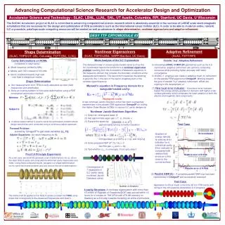
Robust Spin Transport • Developing reliable software tools that allow the machine to be optimised for spin polarisation as well as luminosity. Aiming to carry out full cradle-to-grave simulations. • Currently carrying out simulations of depolarisation effects in damping rings, beam delivery system and during bunch-bunch interactions. • Developing simulations of spin transport through the positron source. • Will soon extend simulations to main linac, etc. Energy spectrum and circular polarisation of photons from helical undulator. Trajectories of electrons through helical undulator. Example of SLICKTRACK simulation showing depolariation of electrons in a ring. • Collaborating with • T. Hartin (Oxford) • P. Bambade, C. Rimbault (LAL) • J. Smith (Cornell) • S. Riemann, A. Ushakov (DESY)
Depolarisation Processes Both stochastic spin diffusion through photon emission and classical spin precession in inhomogeneous magnetic fields can lead to depolarisation. 1 mrad orbital deflection 30° spin precession at 250GeV. Largest depolarisation effects are expected at the Interaction Points. Photon emission Spin precession
Software Tools e+ source Packages in parentheses will be evaluated at a later date.
Positron Source Simulations • Polarisation of photon beam • Ongoing SPECTRA simulations (from SPRING-8) • Benchmarked against URGENT • Depolarisation of e- beam • So far, review of analytical studies only • eg Perevedentsev etal “Spin behavior in Helical Undulator.” (1992) • Target spin transfer • GEANT4 with polarised cross-sections provided by E166 experiment. • Installed and commissioned at University of Liverpool. 10MeV photons
Bunch-Bunch Simulations During Interaction Before Interaction After Interaction Spread in Polarisation Large Y Before Interaction During Interaction After Interaction Low Q • Opposing bunches depolarise one another at the IP(s). • Studies of different possible ILC beam parameters (see table on right). • Much work ongoing into theoretical uncertainties.
SLICKTRACK Simulations • Damping Rings • OCS and TESLA lattices analysed for ILC DR group. • Depolarisation shown to be negligible. • Ongoing rolling study. • Beam Delivery System • First (linear spin motion) simulations presented at EPAC ’06 conference. • Ongoing rolling study.
Future Spin Transport Activities • MERLIN development as a cross-check of main results • Andy Wolski training CI RA’s and PhD students • Non-linear orbital maps interfaced to SLICKTRACK • Modelling sextupoles, octupoles, undulator, etc • Integrated positron source simulations • Rolling study • Beam-beam theoretical uncertainties • Incoherent pair production and EPA, T-BMT validity, etc… • Comparison with GUINEA-PIG • Novel polarisation flipping in positron source • Flipping polarity of source without spin rotators (cost saving) • Polarimetry and polarisation optimisation (University of Lancaster) • Developing techniques to optimise polarisation at the IP • Optimising use of available computing resources at DL, Liverpool and on the GRID
Summary and Outlook • CI has leadership role in many areas of ILC positron source R&D • Recent results presented at EPAC ’06, ICHEP ’06, SPIN ’06, … • Proposed new prototyping programme to be based at Daresbury • Addressing key issues for undulator + target • Establishing base of spin tracking expertise at CI