Download
1 / 32
320 likes | 510 Vues
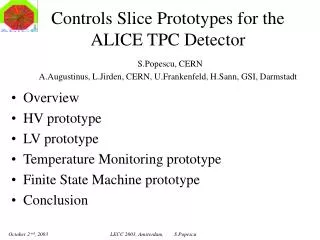
Overview HV prototype LV prototype Temperature Monitoring prototype Finite State Machine prototype Conclusion. Controls Slice Prototypes for the ALICE TPC Detector S.Popescu, CERN A.Augustinus, L.Jirden, CERN, U.Frankenfeld, H.Sann, GSI, Darmstadt. Architecture design and size. ECS. DCS.

E N D
Overview HV prototype LV prototype Temperature Monitoring prototype Finite State Machine prototype Conclusion Controls Slice Prototypes for the ALICE TPC DetectorS.Popescu, CERN A.Augustinus, L.Jirden, CERN, U.Frankenfeld, H.Sann, GSI, Darmstadt LECC 2003, Amsterdam, S.Popescu
Architecture design and size ECS DCS DAQ TRG OFF LHC DET ELE COO GAS INF DSS MAG … ITS TPC TRD TOF HMP PHO ZDC FMD T0 V0 PMD MU EMC COS 19 sub-detectors SPD SDD SSD RO FC CAL CPV TRI TRA ~100 sub-systems … … … … 3-400 device units … … … 2-300 physical devices > 105 channels > 106 parameters LECC 2003, Amsterdam, S.Popescu
Common solutions • HV • LV • Temp. Mon • … DCS … ITS TPC TRD TOF HMP ZDC FMD T0 V0 PMD EMC COS Detectors SPD SDD SSD RO FC PHO MU HV HV HV HV HV HV HV HV HV HV HV HV HV HV HV HV HV HV HV CAL CPV TRI TRA LV LV LV LV LV LV LV LV LV LV LV LV LV LV LV LV LV subsystems FEE FEE FEE FEE FEE FEE FEE FEE FEE FEE FEE FEE FEE MON MON MON MON MON MON MON MON MON MON MON MON MON MON MON MON MON MON MON COO COO COO COO COO COO COO COO COO COO COO COO COO GAS GAS GAS GAS GAS GAS GAS GAS GAS TS LSR ROD TS LIQ ALI PLS TPC Vertical Slice LECC 2003, Amsterdam, S.Popescu
Project overview • 3 main sub-systems in TPC • HV for the chambers • 3 HV crates • 288 channels • Anode 1280 V • Edge 600 V • Skirt 400 V • LV for the Front-End Electronics • 22 crates • 72 channels • Analog 4 V • Digital 3.3 V LECC 2003, Amsterdam, S.Popescu
Project overview • - Cooling for Readout Chambers • cooling circuit for FEC • - 72 PT1000 for FEC circuits • cooling circuit for ROC • - 220 PT1000 (Temp. sensor) for ROC • cooling circuit for Service Support Wheel • - 16 PT1000 for SSW • control and monitoring of water flow • control and monitoring of pressure • control of heater 42 (36 FEC, 4 ROC, 2 SSW) LECC 2003, Amsterdam, S.Popescu
Why building the prototypes? LECC 2003, Amsterdam, S.Popescu
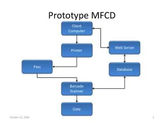
TPC sector test DAQ Cool LV HV FEE FEC Chamber ANALOG DIGITAL ANODE GATING EDGE SKIRT FEE WIENER Chann 4V WIENER Chann 3.3 V ISEG Chann 1280V ISEG Chann 800V ISEG Chann 600V ISEG Chann 400V RCU ECS DCS TPC LECC 2003, Amsterdam, S.Popescu
High Voltage prototype • Main components of the prototype • 1) Hardware configuration • Iseg Crate ECH 238 UPS • Iseg EHQ F025p module • Peak PCI Can Card, 125 Kb, 2ports • PC, Pentium III 700MHz, Can cable • 2) Software configuration • PVSS II • OPC: Iseg v2.02 and custom solution (SLIC.OPC server) • Control software v2.1 • The prototype was used for first tests of the EHQ module. • The behavior of the module for different operational modes has been analyzed . • 3) FSM (Finite State Machine) prototype • It was foreseen the possibility of operatingsingle channels or groups of channels • It was simulated the connection with a database, loading parameters or writing to database • FSM prototype was built as a first test • It was operated with 16 channels connected to the hardware and 69 channels were simulated LECC 2003, Amsterdam, S.Popescu
ISEG EHQ F025p module Connector CanBus HV Module Connector CanBus Crate Controller ISEG ECH 238 crate LECC 2003, Amsterdam, S.Popescu
FSM control panel Local control panel LECC 2003, Amsterdam, S.Popescu
LV prototype • Main components of the prototype • 1) Hardware configuration • Wiener PL500 2-7 V , 2channels, 230 A/channel • Kvaser PCI Can card, 2 ports, 125Kb/s • PC, Pentium III 700MHz, Can cable • 2) Software configuration • PVSS II • OPC – custom solution (SLIC.OPC server) • Control software v2.1 • The prototype was used first for bus bars (40m) measurement. • Will be used for powering up the FEC as soon as the RCU is ready. LECC 2003, Amsterdam, S.Popescu
Temperature monitoring prototype TPC stringent requirement = 0.1 oC stability a reading resolution of ~ 0.04 oC Two hardware solutions were tested: Wago mPLC industrial product ELMB (Embedded Local Monitor Box) developed by ATLAS Comparison test made ELMB chosen for the following reasons: Comparison table LECC 2003, Amsterdam, S.Popescu
T4 T5 T1 T2 T3 Thermal Box T=17 0C PC Windows2000 T6 ELMB OPC server IROC T7 T8 CanBus PVSS client 2.12 Software layout 2) T9 1) Operational Panel 1st ver. Lauda System PUMP T=17 0C 1) IROC circuit System set-up 2) FEC circuit Description of the test: Thermal box : the set-temperature is 17 C with a cooling Lauda system T1,T2,T3on the Pad plane T4in the Thermal Box, T5 between FEC T6in IROC, T7In cool pipe,T8, Out cool pipe T9 room temp LECC 2003, Amsterdam, S.Popescu
Thermal Box T=17 0C IN Cooling pipes OUT Fec cards PS Temp sensors T=17 0C LECC 2003, Amsterdam, S.Popescu
InnerReadout Chamber Prototype FEC Cooling circuit OUT Chamber Cooling circuit LV power lines for FEC FEC Cooling circuit IN Input Cooling circuit Output Cooling circuit LECC 2003, Amsterdam, S.Popescu
ELMB + PT1000 2w connected PT1000 2w sensors connected Can Bus port AI port LECC 2003, Amsterdam, S.Popescu
Results: • High Voltage: • The good news is that the delivered voltages remain unaffected by any communication failures, power cuts etc.. • The software controlled settings correspond to the true physical values (no local display available on crate or module) • Low Voltage: • PS behavior with SLIC.OPC (custom solution) regarding local setting ok • Main constrains : • Company (Wiener) OPC server not available yet • Control of single channels (On/OFF, Error Clearing, Reset…) for the PL500 not possible LECC 2003, Amsterdam, S.Popescu
~30 min Results (continued) Sensor installed on FECs t1,t2,t3 sensors Installed on the PADs plane Heat transfer from FEC to the Chamber during the powering up of the boards. LECC 2003, Amsterdam, S.Popescu
~ 0.18 0C • Results: • heat transfer from FEC cards to pad plane ~ 0.18 0C • relaxation time is approximately 30 minutes • Further investigations need to be done for regulations • studies LECC 2003, Amsterdam, S.Popescu
Controls slices for HV, LV and Temperature Monitoring prototyped for ALICE TPC RO HV slice integrated with Finite State Machine All tested with detector equipment Control principle and choices verified okay Final solution now to be built Solutions to be used by other sub-detectors Conclusion LECC 2003, Amsterdam, S.Popescu
OFF RAMPING_DOWN_EM CONFIGURE EMERGENCY_OFF CONFIG CONFIG_LO ALL STATES CONFIGURE; SET_CONFIGURATION CONFIGURED GO_INTERMEDIATE GO_INTERMEDIATE RECOVER SWITCH_OFF RAMPING_DOWN_LO RAMPING_UP_LO ERROR_LO START SWITCH_OFF INTERMEDIATE START CONFIGURE SET_CONFIGURATION CONFIG_INTERMEDIATE START SWITCH_OFF STOP RECOVER RAMPING_DOWN RAMPING_UP ERROR STOP ON RAMPING_DOWN_CONF STOP CONFIGURE SET_CONFIGURATION CONFIG_ON Appendix HV Channel Description of the State Diagram(1) LECC 2003, Amsterdam, S.Popescu
OFF STOP_HW START_HW HW_READY CONFIGURE CONFIG CONFIGURE SET_CONFIGURATION CONFIGURE SET_CONFIGURATION CONFIG CONFIGURED STOP_HW START_HW GO_INTERMEDIATE SWITCH_OFF RECOVER ERROR NOT_READY RAMPING_DOWN RAMPING_UP START STOP SWITCH_OFF CONFIGURE SET_CONFIGURATION CONFIG INTERMEDIATE START RAMPING_DOWN RAMPING_UP STOP ON Description of the State Diagram(2) LECC 2003, Amsterdam, S.Popescu
FEC’s cooling circuits ROC’s cooling circuits Cooling Plant…. LECC 2003, Amsterdam, S.Popescu
Embedded Local Monitor Board ELMB128 • Technical Data • General-purpose plug-on module (50 x 73 mm2): direct on subdetector FEC or on a general purpose motherboard • CANbus interface (Full-CAN controller) • CANopen communication protocol • In System Programmable also via CAN bus • Optional 64 inputs of 16-bit ADC with 7 bit gain • General I/O • with 18 I/O, 8 Out and 8 IN (or ADC), 3 wire SPI • Flexible power supply circuits incorporated • Radition tolerant up to about 5 Gy and 3*1010 n/cm2 for 10 year • Tolerant in magnetic field up to 1.5 T • Est. cost is < 100 CHF for ADC +CAN • Diagnostic tools available • NI Server Explorer(runs on W2K)-> to have a quick look on OPC items • Canhost: a more dedicate tool(for diagnostics and configuration of ELMB+ bus)-runs on a MS-Dos window • CANalyser : is a universal software for Can bus protocol LECC 2003, Amsterdam, S.Popescu
General purpose motherboard (front side) General purpose motherboard (back side) LECC 2003, Amsterdam, S.Popescu
TPC Low Voltage Distribution Scheme R = 2 x 3.4 mW, DV = 1.32V R = 2 x 6.8 mW, DV = 816mV Voltage on load (V) I stdby (A) I max (A) Bus bar Section (mm2) Bus Bar description What is the transient response of the bus bar? Analogue4.0 60 60 100 Digital3.3 133 194 200 TPC endplate Wiener power supplies L ~ 11mH 121 FEE Cards DIGITAL Bus Bar pair (positive + return line) 115A max DIGITAL 115A max 40m Bus Bar pair ANALOGUE 115A max LECC 2003, Amsterdam, S.Popescu