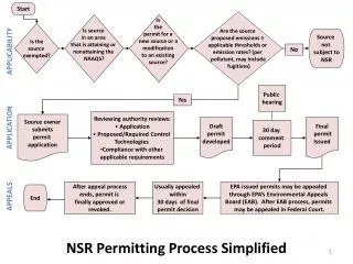
IGCC Process Overview and Permitting Implications for NACAA
IGCC Process Overview and Permitting Implications for NACAA. Tampa FL. May 6, 2008. Tampa Electric Generation. Big Bend Station 1842 Mw 4 Coal-fired steam units (+ CT’s) Bayside Power Station 1650 Mw Repowered NGCC One 3 on 1 One 4 on 1 Polk Power Station 920 Mw One IGCC

IGCC Process Overview and Permitting Implications for NACAA
E N D
Presentation Transcript
IGCC Process Overview andPermitting Implicationsfor NACAA Tampa FL. May 6, 2008
Tampa Electric Generation • Big Bend Station 1842 Mw • 4 Coal-fired steam units (+ CT’s) • Bayside Power Station 1650 Mw • Repowered NGCC • One 3 on 1 • One 4 on 1 • Polk Power Station 920 Mw • One IGCC • Four peaking CT’s (2007) • Phillips Power Station 36 Mw • Two slow-speed diesels • Total capacity (approx.) 4450 Mw 2007 Summer Ratings
Polk Power Station • Unit 1 IGCC, Base load on syngas, intermediate on oil • Combined cycle, GE 7F, 7221 192 MW GE D11, steam 128 MW • Dual fuel, Syngas/Distillate Oil • DOE Clean Coal Technology co-funding $120M • In service 1996 • Unit 2, 3, 4 & 5 Simple Cycle CT, Peaking • Simple cycle GE 7FA+E, 7241 150 MW each • 2 & 3 Dual fuel, Nat gas/Distillate Oil; 4 & 5 Nat Gas only • Unit 2 in service 2000, Unit 3 2002, Units 4 & 5 2007 • Total site over 4000 acres (previously mined for phosphate) • 750 acre cooling pond • 80 Tampa Electric employees
GASIFIER STRUCTURE COAL SILOS SLURRY PREPARATION SULFURIC ACID PLANT OXYGEN PLANT HRSG UNIT 2 CT UNIT 1 CT STEAM TURBINE UNIT 3 CT UNDER CONSTRUCTION N
IGCC – Cleans the “Fuel Gas” not “Flue Gas” • Gasifier at 650 psi • Syngas 1/100th volume of flue gas • Removal equipment smaller and more effective 400 PSIG In Integrated Gasification Combined Cycle (IGCC) plants, gasification converts low cost fuels, like coal, pet coke and biomass into synthesis gas (syngas), and heat to fuel an efficient combined cycle system. In pulverized coal (PC) plants, coal is fed into a boiler, which combusts the coal, followed by post combustion pollution controls. Graphics courtesy of GE Energy
Polk 1 Performance Environmental • Polk rated the “Cleanest Coal-Fired Power Plant in North America” by the Energy Probe Research Foundation (Total emissions from 2002 TRI data)
Low Emissions • Typical Emissions (Lb/MMBTU) Polk Polk Expected (Permit)(Steady State)New IGCC SO2 0.14 0.12 0.019 NOx 0.055 0.04 0.038 Particulate 0.007 <0.004 0.007 Mercury NA NA 90%+ removal (New IGCC values are basis 8,800 hhv btu/kwh net)
Other Environmental Advantages • Beneficial Reuse of Sulfur – H2SO4 at Polk • Beneficial Reuse of Slag • Low Water Use (2/3 that of PC unit) • Minimal solid waste (no gypsum from FGD) • Zero Process Water Discharge
Environmental Opportunities • Mercury - Cost-Effective Removal on IGCC using small activated carbon bed • Testing done at Polk • Commercially at Eastman to 95+% • Other Volatile Metals – Will also be removed by carbon bed
Environmental Opportunities CO2 removal • Solvents for sulfur removal can also remove CO2 • For high levels of removal would “shift” syngas CO + H20→ CO2 + H2 • Shift plus CO2 removal is common for chemicals CO2 Storage (Sequestration) • Deep salt water zone injection – USF feasibility study
Fuel Flexibility • Polk has operated on over 20 different fuels including: Coals Coal Blends Coal/Pet Coke Blends Coal/Coke/Biomass Blends • Slagging gasifier requires somewhat higher fusion temps (Polk targets 2350 – 2700 F T250 temps) • Low rank fuels can be used in slurry fed gasifiers, but hurt efficiency • Power block can operate on syngas or distillate oil
Renewable Fuels Biomass Co-Utilization Tests • Eucalyptus Biomass Test - December, 2001 • Bahiagrass Biomass Test - April, 2004 • (Bahiagrass Harvest and Storage Test started approximately one year prior) • No impact on syngas quality or emissions • Minor issues with material handling
Heat Input to CT is approx 70% of total Feedstock Heating Value 100% Syngas Heating Value 73% of Feedstock Thermal Heat Recovery To Steam Turbine 22% of Feedstock Graphics courtesy of GE Energy
Understanding Heat Input? Power Engineering Magazine, March 2007 Comparing Emissions: PC, CFB and IGCC By: Robynn Andracsek, Burns & McDonnell