Download
1 / 19
190 likes | 210 Vues
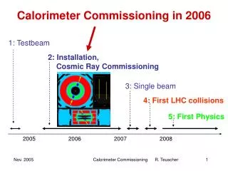
CTF3 commissioning & operation in 2006 P. Ursch ütz for the CTF3 operations team. Commissioning of the Delay Loop Commissioning of the Transfer Line 1 & injection into the Combiner Ring Long pulse, fully beam loaded Linac operation. BPM signals. 0.1. satellites. phase switch. 0.

E N D
CTF3 commissioning & operation in 2006 P. Urschütz for the CTF3 operations team • Commissioning of the Delay Loop • Commissioning of the Transfer Line 1 & injection into the Combiner Ring • Long pulse, fully beam loaded Linac operation
BPM signals 0.1 satellites phase switch 0 -0.1 -0.2 -0.3 (Even bunches) Beam in DL -0.4 main bunches current (A) -0.5 Beam after DL (recombined) -0.6 Odd bunches -0.7 -0.8 -0.9 -1 -1.1 5200 5400 5600 5800 time (ns) Delay Loop commissioning Commissioning status at the end of 2005… • Missing instrumentation: only 6 Beam Pickups installed • out of 17 (one in CT line, 5 in DL) • Beam limited to low current (1 A), short pulse (300 ns) • because of radiation protection reasons • Only one SHB cavity available out of three • Relaxed optics in Delay Loop (non-isochronous) • (2 combined function magnets are wrongly installed… new optics for DL, 3 DL quadrupole families had calibration error) … and plans for 2006 • Additional Instrumentation: more Pickups(+ 2 BPIs in DL) • Re-combination with nominal beam current (3.5 A), long beam pulse (1400 ns) • Sub harmonic bunching with all 3 SHB cavities • Isochronous optics • Measurement of satellite bunch population, time of phase switch in SHBs • Dispersion measurements in DL, bunch length measurements,…
SHB SHB gun SHB buncher 2 accelerating structures Beam combination with transverse RF deflector How does the bunch frequency multiplication work? CTF3 Injector with 3 SHB cavities (1.5 GHz) Phase coding and bunch frequency multiplication in delay loop “phase coding”
Commissioning of the Delay Loop – SHB system Key parameters for the SHB system: 1) time for phase switch < 10 ns (15 1.5 GHz periods) 2) satellite bunch population < 7 % (particles captured in 3 GHz RF buckets) satellite bunch population: phase switch: main bunch satellite bunch Phase switch is done within eight 1.5 GHz periods (<6 ns). Satellite bunch population was estimated to ~8 %.
RF Bandpass filter Diodes 7.5 GHz RF antenna 9 GHz 10.5 GHz e- 12 GHz Delay Loop, path length tuning I DL wiggler has path length tuning range of ~ 9 mm RF phase monitor* after the DL to measure phase error in the RF bunch combination. (*Uppsala University - talk this afternoon by A. Ferrari) measure harmonics of 1.5 GHz
Better RF combination • 7.5 & 10.5GHz • 9 & 12 GHz Delay Loop, path length tuning II Wiggler off Bunches from the DL Bunch from the linac OTR light downstream the Delay Loop Wiggler on Bunches from the DL later by 12ps (3.6mm) Thanks to our BDI guys T.Lefevre, C.Welsch 333 ps
Dispersion measurements I Linac + CT Line • measure reference trajectory at nominal magnet settings • scale magnets by small amount (~1%) • CT Line • Delay Loop • observe difference trajectory • E = 101 MeV magnetic chicane Delay Loop
Dispersion measurements II • In general good agreement between model and measurement • worse in the second half of DL; wiggler or combined function magnet mismatch ? • overall, data for lower currents fits better. • We do not have many BPIs!
SR@ MTV0361 OTR@ MTV0550 “Nominal” chicane - R56 = 0.225 “Natural” chicane - R56 = 0.45 s = 8.9ps (2.7 mm) s = 4.5ps (1.4 mm) Bunch Length measurements – streak camera • bunch length <1.3 mm in the Linac (obtained with cleaning chicane after the injector) • head-to –tail energy correlation is introduced in the accelerator (off crest acceleration & short range wake fields) • magnetic chicane to increase the bunch length before the Delay Loop (up to 2.5 mm) to minimise CSR effects. • measured bunch lengths are very reasonable and change of R56 clearly visible. • head-to–tail energy correlation after the Linac was not the main focus so far (on-crest acceleration). • good agreement to simulations with reasonable initial energy correlation.
2 1 3 Beam recombination • NOMINAL BEAM PARAMETERS ? • Beam current (7 A after DL) 3.3 A max after chicane - 6 A after combination (satellites) • Energy (150 MeV) ~ 100 MeV – still miss MKS 15 – can gain something from others • Emittance (100 π mm mrad) now consistently below nominal (50 - 80 p mm mrad) • Pulse length (1.4 µs) “just” nominal (1.4 ms after chicane, 5 140 ns pulses after DL) • Bunch length (up to 2.5 mm) 1.4 – 2.7 mm (nominal and natural R56 of chicane), • head-to-tail energy correlation of the bunch after the Linac? 2 3 Beam recombination in the Delay Loop (factor 2) 1
Delay Loop - commissioned with beam 2005-2006 Linac - commissioned with beam 2003 - 2004 CRM commissioning – end of 2006 Commissioning of TL1 & CRM TL1 DL CRM • Bypassing the Delay Loop • low gun repetition rate (1 Hz) • No sub harmonic bunchers - 3 GHz beam • beam current: 3.5 A • short pulse length: ~ 200 ns • one additional Klystron (MKS15), higher energy: ~ 125 MeV Just 3 weeks of commissioning – effective 80 hours!
1 2 3 1 2 3 Transmission in TL1 & CRM • 3.2A at the end of CT line. • About 3A after injection into CR (94%). • Magnetic and RF injection (with same transmission). • Nominal, isochronous optics in TL1
Transmission & trajectory in TL1 & CRM Transmission and trajectories from end of CT line to CRM CRM CT TL 1 Beam image at the end of CRM.
TL 1 CRM Dispersion measurements in TL1 & CRM Nominal, isochronous optics in TL1 and we are asking for zero dispersion in CRM. But in operation: non zero dispersion measured in CRM… we always had to change one quadrupole to compensate. Dispersion measurement by magnet scaling within +/- 1% (QFF0690 optimized for zero disp) Drift of the machine, Energy was changing QFF0690 Good agreement for the first part of TL1, discrepancy afterwards. • quadrupole: wrong magnetic field (short in one of the coils). • model: Is it correct? Kick studies with steerers to better understand this discrepancy (to be analysed).
Matching of TL1 & CRM • Quad scan at the end of CT line. • Matching of TL1 and CRM. • Quad scan at the end of CRM. Emittances (εn,rms) in x and y plane between 40 – 80 πmm mrad (nominal 100 πmm mrad) at the end of CT line and CRM! Twiss parameters from measurement and MAD prediction disagree (same problem than for dispersion). What else did we do? • Streak camera studies … talk this afternoon (Carsten Welsch) • Bunch length monitor studies (RF pick up) … talk this afternoon (Mayda Velasco, Anne Dabrowski)
No RF to load RF in High beam current “short” structure - low Ohmic losses HOM damping slot SiC load Fully beam loading operation in CTF3 • CTF3 Drive Beam Acc. Structures (3 GHz) – SICA (Slotted Iris – Constant Aperture): • 32 cells • 1.2 m long • 2π/3 mode • 6.5 MV/m av. acc. gradient for 3.5 A beam current • HOM damping slots Most of RF power to the beam theoretical RF-to-beam efficiency: 96%
Full beam loading operation in CTF3 – Demonstration for CLIC operation MKS05 MKS06 MKS03 MKS07 Spectrometer 4 Spectrometer 10 CLIC: no RF pulse compression length of the drive beam pulse: 100 µs Demonstration at CTF3: Setup: no RF pulse compression for this experiment (with exception of MKS03) 1.5 µs long pulses Adjust RF power and phase and beam current, that fully loaded condition is fulfilled RF pulse at structure input analog signal RF pulse at structure output 1.5 µs beam pulse
Full beam loading operation in CTF3 – Demonstration for CLIC operation Idea: Delay always one klystron pulse after the beam pulse and measure relative energy in spectrometer 10 and compare with calculations. An exact knowledge of the structure input power, the beam current and the energy gain is essential. compare to theoretical energy gain (input power, beam current) total energy • “missing” acceleration (energy gain • per structure) • deceleration due to direct beam loading lower energy from calculations (beam current) measured RF-to-beam efficiency: 95.3 % Theory: 96% (~4 % ohmic losses)
Conclusions Delay Loop: • Fully commissioned with “quasi” nominal parameters (6A re-combined beam current, 1.4 µs pulse length, εn,rms < 100 πmm mrad, tunable bunch length ~ 2mm) • 3 SHB operational, phase switch time < 6 ns, satellite bunches < 8% TL1 & CRM: within short time: • very good transmission until the beam dump • magnetic and RF injection into CRM • small emittances • made important studies with several BDI equipment • but, a better understanding of dispersion and optics has to be obtained Fully beam loaded operation: • very successful demonstration of the long pulse fully loaded operation with an measured RF-to–beam efficiency of 95.3%. Thanks to everybody participating in the commissioning and operation of CTF3 during the 2006 run!